4
$\begingroup$

An excellent review of all of the considerations and work that has gone into designing TESS' orbit can be read in the ArXiv preprint A High Earth, Lunar Resonant Orbit for Lower Cost Space Science Missions and I'll draw primarily from this, and the excellent YouTube video Transiting Exoplanet Survey Satellite (TESS).

For a more in-depth discussion of the details of the mission's orbit, see this answer.

Cropped from the video Transiting Exoplanet Survey Satellite (TESS) at 06:57 this screen shot appears to show a top-down view of TESS' orbit in a way that shows Earth offset from the major axis of the spacecraft's orbit.

Note that the inclination of the orbit is about 37 degrees, but due to its biaxial symmetry tilting an ellipse will not produce this kind of offset, and I don't see quantitatively how the small center-of-mass motion of the Earth in the Earth-Moon barycenter frame can produce a shift of this magnitude, or it's direction either.

Question: Why does Earth not appear to be at the focus of TESS' elliptical orbit in this video?

I've tried to rotate the image and annotate where I think the major axis of the ellipse is by eyeballing it in the first image, only to help illustrate my question.

enter image description here

enter image description here

$\endgroup$
2
  • $\begingroup$ are these pictures to scale? $\endgroup$
    – Muze
    Commented Nov 13, 2018 at 20:45
  • $\begingroup$ I'm pretty sure the horizontal and vertical directions are scaled the same, but there are still two things that can confuse the eye. 1. While orbits are (usually) in a plane, each orbit is in a different plane. So if the Moon's orbit is "flat" then TESSs orbit is tilted and distorted. 2. Often visualization programs use a view that makes things closer look bigger, further distorting the view. What we think should be simple and easy to draw can turn out to be really tricky! $\endgroup$
    – uhoh
    Commented Nov 14, 2018 at 1:06

3 Answers 3

8
$\begingroup$

I believe it is an effect of the used 3d->2d projection and relative angles of the camera and the shown orbit.

I replicated similar Earth center shift using Online Space Orbit Simulator site and changing the default parameters of a random elliptical orbit to make it eccentric and inclined:

  • e = 0.5
  • i = 75

Only the XZ and YZ views seem to keep the Earth in orbit focus for this configuration (afaik because of the 90° argument of perigee) and both XY and the specific perspective projection show Earth shifted quite far from the ellipse focus.

enter image description here

$\endgroup$
4
  • $\begingroup$ Okay, so I could just move your image into my question and ask "Why does Earth not appear to be at the focus of the elliptical orbit in either of these simulations? I usually think of the term "perspective" as a description of the direction of a view. Is it also a projection? (I'm just not sure!) $\endgroup$
    – uhoh
    Commented Apr 10, 2018 at 11:36
  • 2
    $\begingroup$ @uhoh perspective is a 3d->2d projection (not only in computer graphics) with specific features (parallels meeting at infinity, remote object smaller than close ones - natural to human perception) - compared to orthographic projection (keeps the sizes the same at all distances from camera, parallels stay parallel - usually used in blueprints etc.). The "why" then becomes math/3d graphics question. $\endgroup$
    – jkavalik
    Commented Apr 10, 2018 at 11:42
  • $\begingroup$ Indeed you are right, perspective is (also) a projection! I just fired up Blender and saw this: i.sstatic.net/Qgf4G.jpg $\endgroup$
    – uhoh
    Commented Apr 10, 2018 at 11:47
  • 1
    $\begingroup$ And it is a projection which really does NOT keep lot of properties of projected objects - relative sizes, relative distances, right angles.. $\endgroup$
    – jkavalik
    Commented Apr 10, 2018 at 11:52
4
$\begingroup$

3D to 2D is not primary cause. Primary cause is RAAN of two orbits is different. So when you project 3D to 2D, ellipse is slightly rotated. Infact I claim that the angle by which it looks tilted w.r.t to moon orbit is exactly the RAAN difference between two orbits.

$\endgroup$
2
  • 1
    $\begingroup$ I'm not sure I understand. No matter how you tilt an ellipse, the foci will always be on the major axis, and the major axis always bisects the ellipse. I think the choice of certain projections is central to the Earth appearing so offset, though certain RAAN may enhance the effect when viewed from certain directions. $\endgroup$
    – uhoh
    Commented Apr 10, 2018 at 11:52
  • $\begingroup$ Well, yes.. try doing both azimuty and elevation rotation ! $\endgroup$
    – zephyr0110
    Commented Apr 10, 2018 at 13:24
4
$\begingroup$

@jkavalik's answer seems to have nailed it, I'll add my own perspective (no pun intended, seriously!) as background.

When I looked at the problem I first considered and then rejected distortion due to projection (the orbit being much closer to the viewer or camera in some places than in others) because the orbit still looked perfectly elliptical, just displaced.

After resigning myself to the idea that this displacement can in fact be caused by a perspective projection (but not an orthographic projection i.e. looking from very far or infinitely far away), I started to remember reading about the projective plane only a short six months ago and then remembered that I'd read that conics are still conics under projective transformations.

For those "rusty" like me, imagine a perfect, distortionless pinhole camera looking at parallel lines. They are still lines at the camera's film plane and not curved though they are not parallel. See for example Ch. 35 Projective Geometry:

enter image description here

Apparently this works for conic sections as well!

As it turns out, even if one end of an ellipse was very close to the pinhole camera and the other end was far away, it's image would still be an ellipse, or at least a conic at the back of the camera.

This is explained more elegantly in this Math SE answer:

You can map any non-degenerate conic (i.e. it doesn't factor into two lines) and find a homography to any other non-degenerate conic. So you can even map ellipses to hyperbolas and the likes. The mapping won't be unique, but leave you three real degrees of freedom even after both conics have been defined.

So in a visualization with only traces of conic sections, there is no way to distinguish between orthographic and perspective projections. In this case I believe that the use of perspective projection is misguided as it can not provide helpful visual cues, and instead it just adds ambiguity.

It may be helpful in more complex, familiar, or three-dimensional representations, but for planar orbits, I think it's a bad choice.


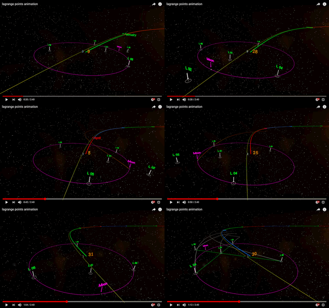
If you look at this video closely, you can see better examples of the effects of perspective projection as well, although because of all the other things going on, it's easy to be distracted. But in the GIF the Earth's orbit looks strangely shaped as a hyperbola rather than a near-circle. Tilting would make it look like a foreshortened circle or ellipse, but with the perspective projection it's ends up looking hyperbolic!

Read more about the tools used to make this video in this answer.

GIF below: Screenshots from the YouTube video lagrange points animation.
enter image description here

A similar effect can be seen in the video Heliospheric Future: Solar Probe Plus & Solar Orbiter after about 01:00.

$\endgroup$

Your Answer

By clicking “Post Your Answer”, you agree to our terms of service and acknowledge you have read our privacy policy.

Not the answer you're looking for? Browse other questions tagged or ask your own question.