16
$\begingroup$

In case of a very specific rotation, even one suffices, but it must be located just right for that specific axis of rotation, and if you want to rotate the satellite, it can do so in that specific axis only, and one direction only.

So, first, assumptions:

  • RCS is the only method of rotational stabilization. If there are any gyroscopes, magnetorquers etc, we don't take them into account.
  • we don't care about translation.
  • the thrusters are not gimballed, vectorable or anything like that - each provides thrust in one direction only.
  • but the moment and power at which they are fired can be very precisely controlled. No negative thrust though, that requires a second thruster.
  • we also have a good information about the attitude changes from the sensors, but the spin/tumble we have entered is arbitrary (within reason, not destructive).
  • for simplicity let's assume a spherical satellite with all mass concentrated in the center, massless thrusters, they may be installed on (massless) trusses extending from the satellite, if need be.

One solution I came up while thinking about this problem requires 5 thrusters.

enter image description here

The cluster of three thrusters can stop any spin/tumble except one going straight through their axis of symmetry (the blue axis). This can be negated by the two thrusters on the "equator".

I have a strong suspicion this can be done with four thrusters though - for example, offsetting the three away from the "pole", that they create a "turbine" pattern, always creating a "polar" spin next to their normal activity, and remove one of the "equatorial" ones.

I wonder if it can be done with even less, or what other layouts would be beneficial.

$\endgroup$
5
  • 1
    $\begingroup$ I suspect four might work too - put them at three equidistant positions on the "45 degree latitude" position. Two will be firing South, and the third position will have two thrusters, offset by an angle so they fire South East and South West. Can't prove this though. (Still thinking very hard about just three; I haven't the mathematical Nouse to prove it.) $\endgroup$
    – Andy
    Commented Mar 11, 2016 at 15:37
  • 1
    $\begingroup$ Also see this (MSL entry module has only four thruster directions - though not entirely clear if this allows full three axis control): solarsystem.nasa.gov/docs/p453.pdf $\endgroup$
    – Andy
    Commented Mar 11, 2016 at 16:23
  • $\begingroup$ @Andy: That looks nice. The setup would be awfully weak against a rotation in this axis (marked pink) but that could be still overcome by offsetting the thrusters farther outwards. Plus this obviously is self-stabilizing in the atmosphere, and suffers heatshield-related compromises. $\endgroup$
    – SF.
    Commented Mar 11, 2016 at 17:38
  • $\begingroup$ @Andy - That, or something like it, does allow full three axis control. These four torque vectors (position $\times$ force = torque) form a regular tetrahedron: $$a:\;(0,+1,+1)\times(+2,+1,-1)=(-2,+2,-2)$$ $$b:\;(0,+1,-1)\times(+2,+1,+1)=(+2,-2,-2)$$ $$c:\;(0,-1,+1)\times(+2,-1,-1)=(+2,+2,+2)$$ $$d:\;(0,-1,-1)\times(+2,-1,+1)=(-2,-2,+2)$$ Fire the thrusters in pairs ($a+b$, $a+c$, $a+d$, $b+c$, $b+d$, $c+d$) to get rotations in both directions around each of the three axes. $\endgroup$
    – mr_e_man
    Commented Jun 6, 2022 at 1:31
  • $\begingroup$ @SF. last bullet point, "all mass concentrated in the center" - If you mean the single point at the centre of the sphere, then that would imply zero rotational inertia, thus infinite rotational acceleration. Instead, I think we want the mass to be uniformly distributed inside the sphere. $\endgroup$
    – mr_e_man
    Commented Jun 6, 2022 at 1:45

4 Answers 4

6
$\begingroup$

Your suspicion that it can be done with 4 is correct, and the method you suggest will work.

More formally, to prove that a set of thrusters allows arbitrary torque is equivalent to showing that you can produce torque in each direction about the 3 orthogonal axes shown.

The ones drawn allow +blue and -blue (the two equatorial thrusters), +green (the one at the top pointing opposite to the red direction) and -green (firing the other two at the top equally). We can then get +red or -red by firing one of these two together with enough of the first one to counteract the -green torque that they also deliver.

In other words the torques from the thrusters are:

  • +B
  • -B
  • +G
  • -aG + bR
  • -aG - bR

(If the thrusters are identical, symmetrically arranged and equidistant from the centre of gravity then a and b are 1/2 and $\sqrt3/2$, but the proof works as long as the two thrusters are symmetric, whatever the values of a and b are.)

If you offset each of the top set by moving each one to the right, each one will also create some +blue torque:

  • +G + cB
  • -aG + bR + cB
  • -aG - bR + cB

Those 3 are still enough to produce any torque you like about the G or R axis (in either direction) but now they will also produce an uncontrolled amount of +blue torque. You can always produce more +blue torque (just increase the thrust of all 3 equally) but never reduce it just by firing these three. However, we now only need one more thruster, -B, to get arbitrary torques in all directions.

$\endgroup$
3
  • $\begingroup$ I have a feeling that a tetrahedral arrangement might be optimal. Imagine a thruster at each of the four corners, and each aimed parallel to a unique adjacent face. $\endgroup$ Commented Mar 12, 2016 at 2:01
  • 2
    $\begingroup$ Is a simple drawing or sketch possible? I can't picture the 4 thruster solution in the question. Thanks! $\endgroup$
    – uhoh
    Commented Mar 12, 2016 at 4:49
  • 1
    $\begingroup$ Yes, I agree that a tetrahedral arrangement would probably be most efficient, at least for providing torque about any arbitrary direction. $\endgroup$
    – djr
    Commented Mar 12, 2016 at 12:27
2
$\begingroup$

I know this question is old, but I randomly discovered a solution requiring only three thrusters on one thruster block that works if we don't mind introducing small transverse velocities.

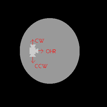
We need a thruster block that has is three thrusters at ninety degrees from each other all tangental to the satellite's surface, or in other words, a typical RCS quad with one thruster deleted.

Operation is the two opposed thrusters can arbitrarily control that plane of rotation and move the remaining thruster to wherever it is needed to change rotation in the remaining plane. (While we think of there being three planes of rotation, in physics there are really two as one of the planes can be produced by adding rotation to the other two.)

This solution has the problem that stabilization takes quite some time as it cannot decide to produce rotation in an arbitrary direction immediately. For this reason it's only really suitable to spin-stabilized craft.

enter image description here

Apologies for my terrible image; the two thrusters CW and CCW obviously control the plane of rotation they are in, while the remaining thruster OHR can be rotated into position by CW and CCW to apply or cancel the rotation component in any other direction.

$\endgroup$
10
  • $\begingroup$ @uhoh: If you make a thruster block and omit one of the four thrusters a thruster block normally will have, two will be opposed and one will not be. $\endgroup$
    – Joshua
    Commented Dec 31, 2020 at 22:33
  • 1
    $\begingroup$ @uhoh: I tried to diagram it. I am a bad artist. $\endgroup$
    – Joshua
    Commented Dec 31, 2020 at 22:46
  • $\begingroup$ Great! Thank you :-) I have a hunch that this is the/a right answer, but it may take some time for a mathematical proof to be forthcoming. +1 $\endgroup$
    – uhoh
    Commented Dec 31, 2020 at 23:02
  • 1
    $\begingroup$ @uhoh: I don't have a proof that an asymmetrical two-thruster unit doesn't work, but I couldn't get one to work. $\endgroup$
    – Joshua
    Commented Dec 31, 2020 at 23:16
  • $\begingroup$ This is a different question altogether, but related: Does a single off-axis thruster firing continuously eventually stabilize attitude gyroscopically? $\endgroup$
    – uhoh
    Commented Dec 31, 2020 at 23:26
0
$\begingroup$

The surprisingly low answer is: 2. But it is very unpractical and not enough redundant.

The reasoning is very simple.

The angular velocity vector has 3 degrees of freedom, but its length (the absolute value of the angular velocity) does not count. Bigger deviation from the expected can be compensated by a longer RCS fire.

1 would be surely not enough, it could only rotate the spacecraft around a single axis.

$\endgroup$
4
  • $\begingroup$ The "degrees of freedom" reasoning may run into trouble because thrusters cannot be fired in an arbitrary linear combination. (You can't have negative coefficients.) $\endgroup$ Commented Jun 7, 2021 at 18:44
  • $\begingroup$ @CharlesStaats That is very strong reason for the impracticality, but not for the impossibility. In orientation: making a nearly 360 degree is the same than making a negative degree. In angular velocity: making a 180 degree rotation on the perpedicular direction, then the required burst, then turning back (I think the optimal RCS sequence is probably much more complex, but still very impractical). $\endgroup$
    – peterh
    Commented Jun 7, 2021 at 19:16
  • $\begingroup$ @CharlesStaats Adding yet another thruster, call it $C$, could solve this problem if its direction is the opposite of the other thrusters combined ($-A-B$). This would be still a propellant waste (the thrusters would work partially against each other). I would say for 4 thrusters that it is not a big propellant waste. The optimal number of the thrusters is infinite (so there is always a thruster in the exactly to compensatable axis and direction). $\endgroup$
    – peterh
    Commented Jun 7, 2021 at 19:25
  • $\begingroup$ I'm not saying it is impossible. I'm saying your "simple" reasoning in the body of the answer fails to show it is possible, only that it is somewhat plausible. The construction you start in the comments is headed in the right direction, but I'm not sure if it works or not. $\endgroup$ Commented Jun 7, 2021 at 23:49
-1
$\begingroup$

Answer: 3 thrusters are adequate to control attitude, and provide translational thrust as well.

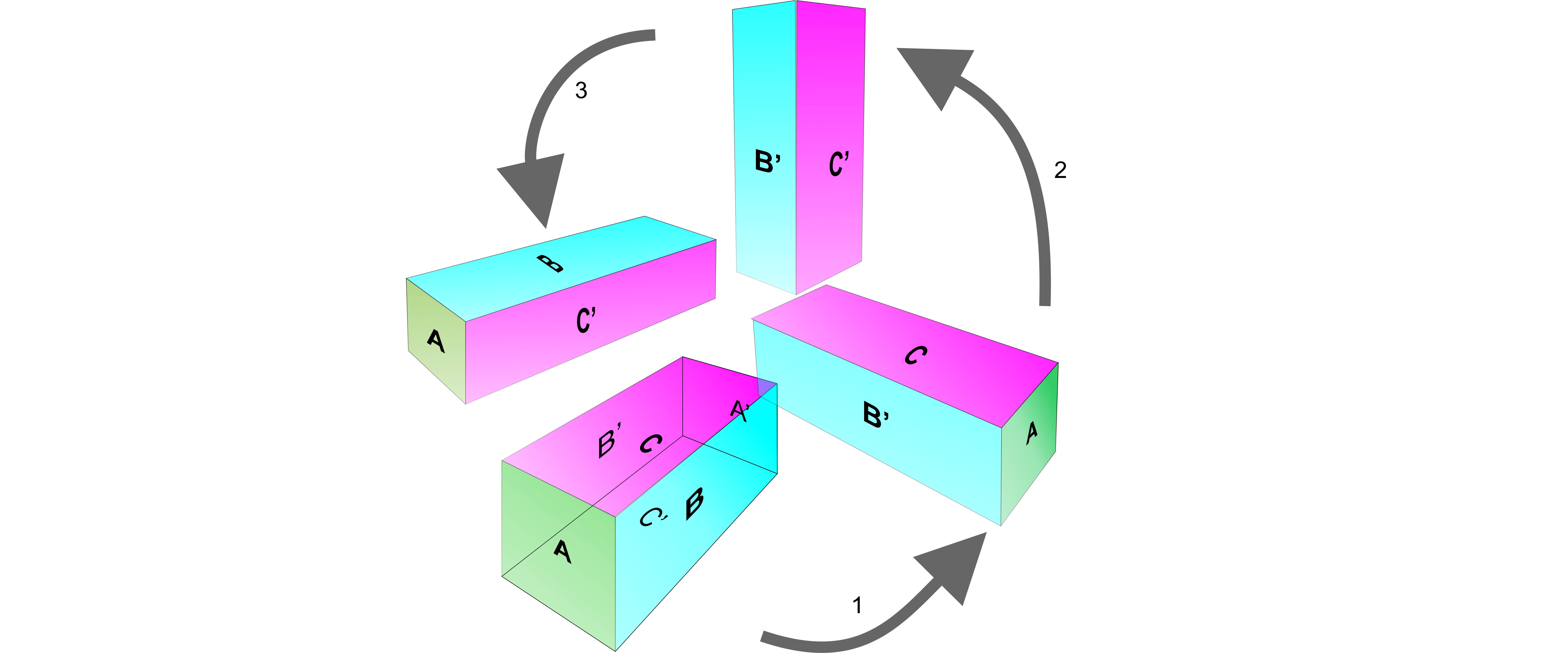
The sketch below shows a spacecraft with a single cluster of 3 thrusters. Opposite sides of the craft have the same colors, but are distinguished by A,A’ B,B’ and C,C’

enter image description here

By using combinations of one or two thrusters, rotation can be achieved around the blue faces or the pink faces (B-B’ and C-C’ axis).

Rotation around the green faces is trickier, but can be done similar to the way a cat lands on its feet. Below, using 3 steps, the blue face B is rotated from the side the the zenith.

enter image description here

The 3 thrusters could be angled into a tetrahedral shape, as in the sketch below. They retain the ability to change attitude as before. But now, if fired together, they (inefficiently) generate thrust through the COM and can therefore produce translational thrust as well as attitude control.

enter image description here

$\endgroup$
1
  • $\begingroup$ This can change the angular position around the $A$ axis, but not the angular velocity around the $A$ axis. So it doesn't quite work. $\endgroup$
    – mr_e_man
    Commented Dec 23, 2022 at 4:33

Your Answer

By clicking “Post Your Answer”, you agree to our terms of service and acknowledge you have read our privacy policy.

Not the answer you're looking for? Browse other questions tagged or ask your own question.