added 5 characters in body
Source Link
Bob Jacobsen
  • 12.9k
  • 2
  • 34
  • 58

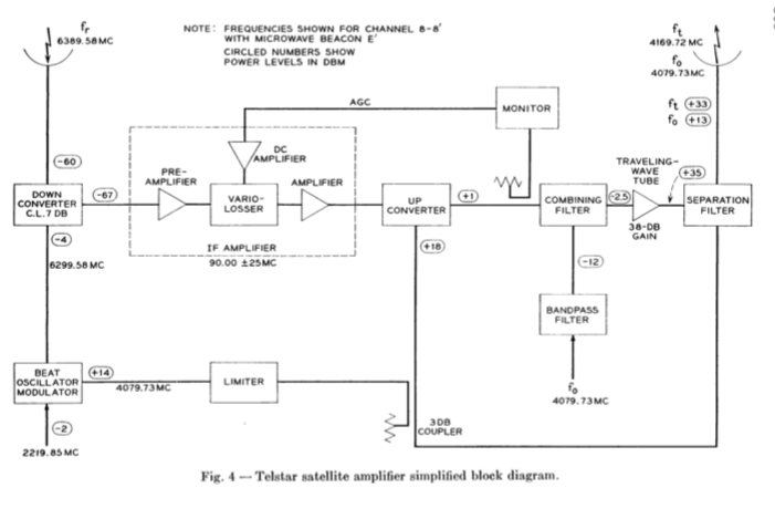
Telstar 1 carried a single transponder with 6390MHz uplink and 4170MHz downlink.

All the 72 ports in the small-aperture ring were ganged together to make a single receive antenna with a toroidal pattern that extended 30 degrees above/below the equator of the satellite, but had even gain as the satellite spun.

The 48 ports in the larger-aperture ring worked the same way for transmit.

The overall energy budget was amazingly marginal. The solar cells only provided 14W, feeding a 3W TWT. There was no power (and probably no weight budget) to do anything other than to make the antennas from passively combined ports in a time before high-frequency semiconductorsmicrowave semiconductor amplifiers. The satellite had to be spin stabilized (with a passive coning damper), and there was no way to aim a higher gain antenna.

enter image description here

Source: "A General Description of the Telstar Spacecraft", R.H. Shennum and P.T. Haury, 1963, published in NASA SP-32 p.801. See particularly Figure 4 on page 806 which shows the single transponder circuit, and section VII (pp 812-816) on antennas, which includes as Figure 6 the top image in the question and the pattern described above as Figure 7 and 8.
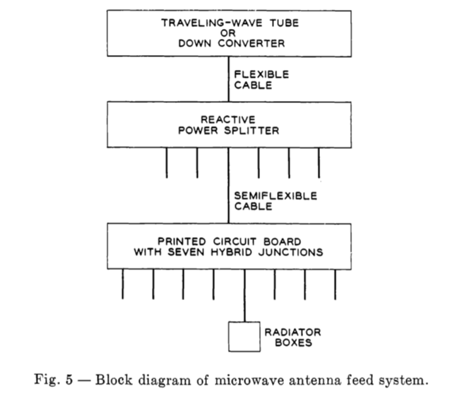
enter image description here For more technical detail, please see "The Spacecraft Antennas", J.T. Bangert, R.S. Engelbrecht, E.T. Harkless (yes, that Harkless), R.V. Sperry and E.J. Walsh, 1963, published in NASA SP-32 p.869.
Telstar 1 carried a single transponder with 6390MHz uplink and 4170MHz downlink.

All the 72 ports in the small-aperture ring were ganged together to make a single receive antenna with a toroidal pattern that extended 30 degrees above/below the equator of the satellite, but had even gain as the satellite spun.

The 48 ports in the larger-aperture ring worked the same way for transmit.

The overall energy budget was amazingly marginal. The solar cells only provided 14W, feeding a 3W TWT. There was no power (and probably no weight budget) to do anything other than to make the antennas from passively combined ports in a time before high-frequency semiconductors. The satellite had to be spin stabilized (with a passive coning damper), and there was no way to aim a higher gain antenna.

enter image description here

Source: "A General Description of the Telstar Spacecraft", R.H. Shennum and P.T. Haury, 1963, published in NASA SP-32 p.801. See particularly Figure 4 on page 806 which shows the single transponder circuit, and section VII (pp 812-816) on antennas, which includes as Figure 6 the top image in the question and the pattern described above as Figure 7 and 8.

enter image description here For more technical detail, please see "The Spacecraft Antennas", J.T. Bangert, R.S. Engelbrecht, E.T. Harkless (yes, that Harkless), R.V. Sperry and E.J. Walsh, 1963, published in NASA SP-32 p.869.

Telstar 1 carried a single transponder with 6390MHz uplink and 4170MHz downlink.

All the 72 ports in the small-aperture ring were ganged together to make a single receive antenna with a toroidal pattern that extended 30 degrees above/below the equator of the satellite, but had even gain as the satellite spun.

The 48 ports in the larger-aperture ring worked the same way for transmit.

The overall energy budget was amazingly marginal. The solar cells only provided 14W, feeding a 3W TWT. There was no power (and probably no weight budget) to do anything other than to make the antennas from passively combined ports in a time before microwave semiconductor amplifiers. The satellite had to be spin stabilized (with a passive coning damper), and there was no way to aim a higher gain antenna.

enter image description here

Source: "A General Description of the Telstar Spacecraft", R.H. Shennum and P.T. Haury, 1963, published in NASA SP-32 p.801. See particularly Figure 4 on page 806 which shows the single transponder circuit, and section VII (pp 812-816) on antennas, which includes as Figure 6 the top image in the question and the pattern described above as Figure 7 and 8.

enter image description here For more technical detail, please see "The Spacecraft Antennas", J.T. Bangert, R.S. Engelbrecht, E.T. Harkless (yes, that Harkless), R.V. Sperry and E.J. Walsh, 1963, published in NASA SP-32 p.869.

added 450 characters in body
Source Link
Bob Jacobsen
  • 12.9k
  • 2
  • 34
  • 58

Telstar 1 carried a single transponder with 6390MHz uplink and 4170MHz downlink.

All the 72 ports in the small-aperture ring were ganged together to make a single receive antenna with a toroidal pattern that extended 30 degrees above/below the equator of the satellite, but had even gain as the satellite spun.

The 48 ports in the larger-aperture ring worked the same way for transmit.

The overall energy budget was amazingly marginal. The solar cells only provided 14w14W, feeding a 3w3W TWT. TheThere was no power (and probably no weight budget) to do anything other than to make the antennas from passively combined ports in a time before high-frequency semiconductors. The satellite had to be spin stabilized (with a passive coning damper), and there was no way to aim a higher gain antenna.

enter image description here

Source: "A General Description of the Telstar Spacecraft", R.H. Shennum and P.T. Haury, 1963, published in NASA SP-32 p.801. See particularly Figure 4 on page 806 which shows the single transponder circuit, and section VII (pp 812-816) on antennas, which includes as Figure 6 the top image in the question and the pattern described above as Figure 7 and 8.

enter image description here For more technical detail, please see "The Spacecraft Antennas", J.T. Bangert, R.S. Engelbrecht, E.T. Harkless (yes, that Harkless), R.V. Sperry and E.J. Walsh, 1963, published in NASA SP-32 p.869.

Telstar 1 carried a single transponder with 6390MHz uplink and 4170MHz downlink.

All the 72 ports in the small-aperture ring were ganged together to make a single receive antenna with a toroidal pattern that extended 30 degrees above/below the equator of the satellite, but had even gain as the satellite spun.

The 48 ports in the larger-aperture ring worked the same way for transmit.

The overall energy budget was amazingly marginal. The solar cells only provided 14w, feeding a 3w TWT. The satellite had to be spin stabilized (with a passive coning damper), and there was no way to aim a higher gain antenna.

enter image description here

Source: "A General Description of the Telstar Spacecraft", R.H. Shennum and P.T. Haury, 1963, published in NASA SP-32 p.801. See particularly Figure 4 on page 806 which shows the single transponder circuit, and section VII (pp 812-816) on antennas, which includes as Figure 6 the top image in the question and the pattern described above as Figure 7 and 8.

enter image description here For more technical detail, please see "The Spacecraft Antennas", J.T. Bangert, R.S. Engelbrecht, E.T. Harkless (yes, that Harkless), R.V. Sperry and E.J. Walsh, 1963, published in NASA SP-32 p.869.

Telstar 1 carried a single transponder with 6390MHz uplink and 4170MHz downlink.

All the 72 ports in the small-aperture ring were ganged together to make a single receive antenna with a toroidal pattern that extended 30 degrees above/below the equator of the satellite, but had even gain as the satellite spun.

The 48 ports in the larger-aperture ring worked the same way for transmit.

The overall energy budget was amazingly marginal. The solar cells only provided 14W, feeding a 3W TWT. There was no power (and probably no weight budget) to do anything other than to make the antennas from passively combined ports in a time before high-frequency semiconductors. The satellite had to be spin stabilized (with a passive coning damper), and there was no way to aim a higher gain antenna.

enter image description here

Source: "A General Description of the Telstar Spacecraft", R.H. Shennum and P.T. Haury, 1963, published in NASA SP-32 p.801. See particularly Figure 4 on page 806 which shows the single transponder circuit, and section VII (pp 812-816) on antennas, which includes as Figure 6 the top image in the question and the pattern described above as Figure 7 and 8.

enter image description here For more technical detail, please see "The Spacecraft Antennas", J.T. Bangert, R.S. Engelbrecht, E.T. Harkless (yes, that Harkless), R.V. Sperry and E.J. Walsh, 1963, published in NASA SP-32 p.869.

added 450 characters in body
Source Link
Bob Jacobsen
  • 12.9k
  • 2
  • 34
  • 58

Telstar 1 carried a single transponder with 6390MHz uplink and 4170MHz downlink.

All the 72 ports in the small-aperture ring were ganged together to make a single receive antenna with a toroidal pattern that extended 30 degrees above/below the equator of the satellite, but had even gain as the satellite spun.

The 48 ports in the larger-aperture ring worked the same way for transmit.

The overall energy budget was amazingly marginal. The solar cells only provided 14w, feeding a 3w TWT. The satellite had to be spin stabilized (with a passive coning damper), and there was no way to aim a higher gain antenna.

enter image description here

Source: "A General Description of the Telstar Spacecraft""A General Description of the Telstar Spacecraft", R.H. Shennum and P.T. Haury, 1963, published in NASA SP-32 p.801 1963. See particularly Figure 4 on page 806 which shows the single transponder circuit, and section VII (pp 812-816) on antennas, which includes as Figure 6 the top image in the question and the pattern described above as Figure 7 and 8.

enter image description here For more technical detail, please see "The Spacecraft Antennas", J.T. Bangert, R.S. Engelbrecht, E.T. Harkless (yes, that Harkless), R.V. Sperry and E.J. Walsh, 1963, published in NASA SP-32 p.869.

Telstar 1 carried a single transponder with 6390MHz uplink and 4170MHz downlink.

All the 72 ports in the small-aperture ring were ganged together to make a single receive antenna with a toroidal pattern that extended 30 degrees above/below the equator of the satellite, but had even gain as the satellite spun.

The 48 ports in the larger-aperture ring worked the same way for transmit.

The overall energy budget was amazingly marginal. The solar cells only provided 14w, feeding a 3w TWT. The satellite had to be spin stabilized (with a passive coning damper), and there was no way to aim a higher gain antenna.

Source: "A General Description of the Telstar Spacecraft", R.H. Shennum and P.T. Haury, 1963, published in NASA SP-32 p.801 1963. See particularly Figure 4 on page 806 which shows the single transponder circuit, and section VII (pp 812-816) on antennas, which includes as Figure 6 the top image in the question and the pattern described above as Figure 7 and 8.

Telstar 1 carried a single transponder with 6390MHz uplink and 4170MHz downlink.

All the 72 ports in the small-aperture ring were ganged together to make a single receive antenna with a toroidal pattern that extended 30 degrees above/below the equator of the satellite, but had even gain as the satellite spun.

The 48 ports in the larger-aperture ring worked the same way for transmit.

The overall energy budget was amazingly marginal. The solar cells only provided 14w, feeding a 3w TWT. The satellite had to be spin stabilized (with a passive coning damper), and there was no way to aim a higher gain antenna.

enter image description here

Source: "A General Description of the Telstar Spacecraft", R.H. Shennum and P.T. Haury, 1963, published in NASA SP-32 p.801. See particularly Figure 4 on page 806 which shows the single transponder circuit, and section VII (pp 812-816) on antennas, which includes as Figure 6 the top image in the question and the pattern described above as Figure 7 and 8.

enter image description here For more technical detail, please see "The Spacecraft Antennas", J.T. Bangert, R.S. Engelbrecht, E.T. Harkless (yes, that Harkless), R.V. Sperry and E.J. Walsh, 1963, published in NASA SP-32 p.869.

added 375 characters in body
Source Link
Bob Jacobsen
  • 12.9k
  • 2
  • 34
  • 58
Loading
Source Link
Bob Jacobsen
  • 12.9k
  • 2
  • 34
  • 58
Loading