13
$\begingroup$

What systems are used for range, speed and alignment when docking in orbit? Whether automatic, human controlled arm, or Apollo style human controlled ship to ship?

Playing Kerbal Space Program, I have my speed, range, and direction in game. Granted docking is still somewhat difficult, keeping all of these things in range.

I'm wondering, when docking to the ISS, or even earlier stations, what systems were used to enable docking? When trying to dock in game, I need to know, at the very least, my speed and my range. Lately they have been using Dragon (SpaceX?) docking capsules to resupply the ISS. What systems are used remotely or robotically to dock these modules?
$\endgroup$
4
  • $\begingroup$ Docking of Soyuz and Progress is generally automatic: en.wikipedia.org/wiki/Kurs_(docking_navigation_system) $\endgroup$ Commented Aug 7, 2015 at 17:15
  • $\begingroup$ Dragon is grabbed by an arm and pulled in under human control from the station. csmonitor.com/Science/2015/0112/… -- that's not a feature of vanilla KSP, but you could probably set it up using a mod like Infernal Robotics. $\endgroup$ Commented Aug 7, 2015 at 17:18
  • $\begingroup$ Shut down the radar and just hope for the best Russian style. But you might be a more serious game player than Roscosmos was. $\endgroup$
    – LocalFluff
    Commented Aug 7, 2015 at 17:30
  • 1
    $\begingroup$ @RussellBorogove You can do it in vanilla with multiple vessels locked in a pivot joint. A bit tricky but doable. I remember some player did a Canadarm replica in stock. $\endgroup$ Commented Aug 7, 2015 at 20:53

3 Answers 3

11
$\begingroup$

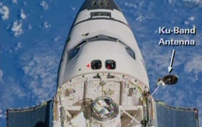
Shuttle, for rendezvous sensors, used the Ku-band in radar mode and an optical sight (the Crewman Optical Alignment Sight or COAS).

enter image description here

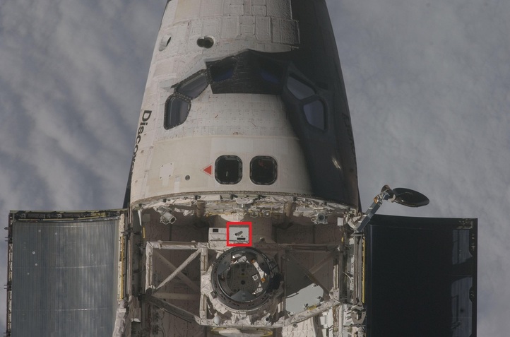
Closer in there was a laser radar mounted on the docking system called the Trajectory Control System (TCS) that used reflectors mounted on the target vehicle to get range and range rate. (The highlighted box is a different rendezvous sensor being tested, the TCS is the white box with a dark rectangular window to its left).

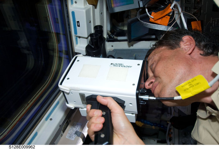
enter image description here This was later supplemented by a hand-held LIDAR to give range and range rate (basically a modified police laser speed detector).

enter image description here

Early on this was also done by triangulating CCTV cameras from the payload bay and using an overlay on the TV monitors...but I believe this was considered a backup method by late in the program, as I don't recall much training on it being done, as opposed to the TCS.

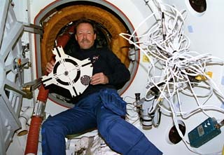
Finally, for the last few feet, there was a optical docking target, viewed through a CCTV camera looking up through the airlock hatch window.

enter image description here

Good narrative description here.

And just for coolness, the rendezvous flip maneuver (sped up)

$\endgroup$
6
  • 2
    $\begingroup$ what's the point of the flip manoeuver? $\endgroup$
    – njzk2
    Commented Aug 8, 2015 at 3:56
  • 3
    $\begingroup$ It was so the crew in the ISS could take pictures of the shuttle tiles - part of the safeguards put in after the Columbia accident. $\endgroup$ Commented Aug 8, 2015 at 4:01
  • $\begingroup$ I've been looking for a good centerline target CONOPs description--camera overlay, standoff cross, parallax, etc, but can't find one. $\endgroup$
    – Erin Anne
    Commented Aug 12, 2015 at 1:27
  • $\begingroup$ @ErinAnne Can you get hold of USA00604 Rendezvous Crew Training Handbook? Surely everything at JSC hasn't gone down the memory hole. $\endgroup$ Commented Aug 12, 2015 at 1:41
  • 1
    $\begingroup$ I meant I was looking for a publicly available document, to add to the answer. Though the memory hole yet grows. $\endgroup$
    – Erin Anne
    Commented Aug 13, 2015 at 1:46
7
$\begingroup$

My favorite reference for this is JSC 63400 "History of Space Shuttle Rendezvous," available http://ntrs.nasa.gov/archive/nasa/casi.ntrs.nasa.gov/20110023479.pdf

Some highlights (page numbers for Rev 3):

  • TACAN transmitters and radar transponders were considered for cooperative targets during the Shuttle program (pg 83)
  • Pg 89 shows several of the (mostly text) computer displays used by shuttle during rendezvous and prox ops (RPO). Very Mechjeb.
  • Pg 108 introduces PLBay, which became RPOP, a situational awareness program I now work on. The program shows where the spacecraft has been, where it will go...useful for relative mechanics, which aren't always intuitive. Pictures of what RPOP looks like are on Pgs 134, 238 (baaaarely), 239 (much more obvious in-use view illustration), 241 (closer in), 243, 244, 249-252.
  • Pg 225 starts a VERY in-depth look at a pretty typical Shuttle-to-ISS mission. Long story short is that RPOD (rendezvous, prox ops and docking) starts with pre-launch math to identify favorable docking opportunities, and then a lot of exacting measurement using all the things Organic Marble mentioned, plus a lot of supporting instruments to transform that data into things that the crew can understand and fly.
$\endgroup$
0
2
$\begingroup$

The most commonly used system is either Radar or LIDAR, both of which will get the range and velocity of the differing target very accurately. LIDAR is a bit better, and will give you a larget image.

Alignment is a bit trickier, but again, the same systems, LIDAR and Radar, are the primary systems used.

$\endgroup$
2
  • $\begingroup$ What is the difference between Radar and LIDAR? And can/how these do anything to help with alignment? $\endgroup$
    – CDspace
    Commented Aug 7, 2015 at 18:36
  • $\begingroup$ Radar uses radio/ microwaves, LIDAR uses Lasers. Lasers are more accurate, in general, but require more precision. They can help by detecting the shape of the object, although I should do a bit more research on the subject... $\endgroup$
    – PearsonArtPhoto
    Commented Aug 7, 2015 at 18:42

Your Answer

By clicking “Post Your Answer”, you agree to our terms of service and acknowledge you have read our privacy policy.

Not the answer you're looking for? Browse other questions tagged or ask your own question.