3
$\begingroup$

Discussion in comments below this answer relate to how much solid rockets or SRBs burn bottom-to-top versus radially outward.

I am sure I've seen a diagram somewhere showing that different designs are different in this aspect, and that in some cases there was an advantage for the lower part to burn radially faster than the top in order to allow for "better flow" but I really can't remember exactly how the discussion went.

Am I imagining things and all SRBs quickly start burning throughout the length, and the burn rate is uniform along the whole length and strictly radial? Or are there some designs where the mass at the bottom will disappear faster than that at the top, resulting in at least a small but significant translation upward of the center-of-mass?

If this does happen, it would be great to have an example or extreme case where this happens more than for typical SRB burn patterns.

$\endgroup$
5
  • 2
    $\begingroup$ Are you thinking of grain geometry? Perhaps from this question? $\endgroup$
    – called2voyage
    Commented Sep 12, 2018 at 16:48
  • $\begingroup$ @called2voyage what I am either remembering or mis-remembering is a diagram in cross-section after say 50% of the mass has burned, showing that the remaining fuel at the bottom is less than at the top, thus the center of mass moved upwards. I don't see that in either link (yet) I'll look closer now. $\endgroup$
    – uhoh
    Commented Sep 12, 2018 at 16:53
  • 2
    $\begingroup$ @called2voyage it could have been very, very long ago like on an insert in an Estes rocket engine pack even. update: ha! this is in one of the answers to your linked question! spaceflightsystems.grc.nasa.gov/education/rocket/… There's a GIF there too! $\endgroup$
    – uhoh
    Commented Sep 12, 2018 at 16:56
  • 1
    $\begingroup$ Related: for the Shuttle SRB I got an angle of 2.6º off the vertical for the wall angle of the bore. space.stackexchange.com/questions/10829/… $\endgroup$
    – Hobbes
    Commented Sep 12, 2018 at 17:25
  • $\begingroup$ @Hobbes The GIF on le_daim's answer is nice. It would be interesting to see that view for different grain geometries. $\endgroup$
    – called2voyage
    Commented Sep 12, 2018 at 18:31

2 Answers 2

5
$\begingroup$

Shuttle SRB had a deeply grooved section at the front of the booster, and a tapering bore section at the back.

This diagram is for a cancelled lightweight filament-wound booster for high-payload STS flights (FWC-SRM), but the standard STS SRB I believe has a generally similar cross section:

enter image description here

Thrust is generally proportional to burning surface area. The grooved section provides a lot of surface area at the start for high thrust, but burns out quickly, leading to a drop-off in thrust which I believe corresponds to the start of the "throttle bucket". The central cylindrical bore will increase in surface area gradually over the course of the burn, but the tapered section towards the back will reduce the burning length as it goes, balancing that out for a more level thrust profile.

The center of gravity of this grain profile would thus drop backwards pretty rapidly then move slowly forwards again, but the overall CG movement should be fairly small.

$\endgroup$
1
  • $\begingroup$ Ah, it took me a minute to realize that the two parts in the first drawing are the "bottom half" and "top half" of one SRB, total of four segments. It also took me a minute to convert between front/back and top/bottom, but front/back is definitely the better way to say it, since hopefully rockets do not remain on the launch pad forever. $\endgroup$
    – uhoh
    Commented Sep 13, 2018 at 1:54
4
$\begingroup$

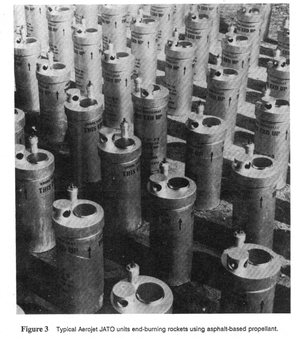
Early solid Jet Assisted Takeoff (JATO) (aka Rocket...) (RATO) units were end-burning; in other words, the casing was simply filled with solid fuel without a shaped grain and ignition took place at the end.

This type of solid rocket would experience a CG movement along the longitudinal axis of the casing as the propellant was expended. However, these boosters were typically small compared to the boosted vehicle so perhaps the CG movement was not a big concern.

enter image description here

Image source

enter image description here

Image source

$\endgroup$
4
  • 1
    $\begingroup$ Ask (for an extreme case) and you shall receive! I've just asked What exactly are these engineers doing $\endgroup$
    – uhoh
    Commented Sep 13, 2018 at 1:45
  • 1
    $\begingroup$ @uhoh I'm trying very hard not to look at aviation stack exchange since I spend enough time on my primary 3 stacks already! $\endgroup$ Commented Sep 13, 2018 at 1:56
  • 1
    $\begingroup$ 4,000+ views; you always find interesting goodies and sources! $\endgroup$
    – uhoh
    Commented Sep 13, 2018 at 18:16
  • 2
    $\begingroup$ @uhoh That's an interesting picture; I interviewed for a job at the General Dynamics plant in Fort Worth long ago. Boxcars of parts came in at one end and F-16 fighters went out the other. Walking around that huge, huge factory floor was unforgettable, I'm sure a large transport /bomber factory is even more so. $\endgroup$ Commented Sep 13, 2018 at 18:29

Your Answer

By clicking “Post Your Answer”, you agree to our terms of service and acknowledge you have read our privacy policy.

Not the answer you're looking for? Browse other questions tagged or ask your own question.