7
$\begingroup$

The now-famous answer to How is stacking oranges in 24 dimensions related to receiving and decoding signals from the Voyagers? is worth stopping now here and going back and reading first.

Okay welcome back! @NgPh's comment under the question links to Channel Coding: The Road to Channel Capacity which is also very much worth reading. It says:

E. Reed-Solomon code implementations

The first major application of RS codes was as outer codes in concatenated coding systems for deep-space communications. For the 1977 Voyager mission, the Jet Propulsion Laboratory (JPL) used a (255, 223, 33), 16-error-correcting RS code over $\mathbb{F}_{256}$ as an outer code, with a rate-1/2, 64-state convolutional inner code (see also Section IV-D). The RS decoder used special-purpose hardware for decoding, and was capable of running up to about 1 Mb/s [27]. This concatenated convolutional/RS coding system became a NASA standard.

1980 saw the first major commercial application of RS codes in the compact disc (CD) standard. This system used two short RS codes over $\mathbb{F}_{256}$, namely (32, 28, 5) and (28, 24, 5) RS codes, and operated at bit rates of the order of 4 Mb/s [28]. All subsequent audio and video magnetic storage systems have used RS codes for error correction, nowadays at much higher rates.

[...] Linkabit Corp. was founded by Irwin Jacobs, Len Kleinrock, and Andy Viterbi in 1968 as a consulting company. In 1969, Jerry Heller was hired as Linkabit’s first full-time employee. Shortly thereafter, Linkabit built a prototype 64-state Viterbi algorithm decoder (“a big monster filling a rack” [60]), capable of running at 2 Mb/s [61].

  • [27]:R. W. McEliece and L. Swanson, “Reed-Solomon codes and the exploration of the solar system,” in Reed-Solomon Codes and Their Applications (S. B. Wicker and V. K. Bhargava, eds.), pp. 25–40. Piscataway, NJ: IEEE Press, 1994.
  • [28]:K. A. S. Immink, “Reed-Solomon codes and the compact disc,” in Reed-Solomon Codes and Their Applications (S. B. Wicker and V. K. Bhargava, eds.), pp. 41–59. Piscataway, NJ: IEEE Press, 1994.
  • [60]:D. Morton, “Andrew Viterbi, electrical engineer: An oral history,” IEEE History Center, Rutgers U., New Brunswick, NJ, Oct. 1999
  • [61]:J. A. Heller and I. M. Jacobs, “Viterbi decoding for satellite and space communication,” IEEE Trans. Commun. Tech., vol. COM–19, pp. 835–848, Oct. 1971.

Question: What Voyager spacecraft hardware performed transmitted data coding in such a complicated way? Did ground decoding use “a big monster filling a rack”?

I'm interested in seeing and/or reading about the hardware (and software if possible) that implemented encoding aboard the Voyager spacecraft and that which implemented decoding on the ground. Aboard the Voyagers, was it a tiny computer and a nice bit of code, or was coding done with a hardware implementation?
$\endgroup$
9
  • 2
    $\begingroup$ A Reed-Solomon hardware encoder was included on Voyager, even though software was not included for it at launch, but according to this page, no picture exists or could be found. It does have a layout of the RS encoder though. meh.com/forum/topics/building-the-plane-on-the-way-up $\endgroup$ Commented Jul 10, 2021 at 4:40
  • 1
    $\begingroup$ @blobbymcblobby that seems to be the beginnings of the answer, thanks for the great link! $\endgroup$
    – uhoh
    Commented Jul 10, 2021 at 5:49
  • 1
    $\begingroup$ @DavidHammen "What hardware..." is a great question. The way that the hardware encodes sounds complicated to me, so I want to see the actual encoding hardware to see if it is also looks complciated, or if it turns out to be quite simple, and if the encoding is done with hardware or with software. It's a great question, looking forward to seeing the answer. $\endgroup$
    – uhoh
    Commented Jul 10, 2021 at 15:34
  • 1
    $\begingroup$ @DavidHammen I understand what you are saying, but I do not understand why that would make this not a good question. $\endgroup$ Commented Aug 17, 2023 at 2:45
  • 1
    $\begingroup$ @blobbymcblobby "It does have a layout of the RS encoder though. meh.com/forum/topics/building-the-plane-on-the-way-up" -- Of note, the chip layout image given by that page is not the Voyager R-S circuit; it is a chip built in the mid 1980s. The figure is from Hsu et al. 1987, "A VLSl Single Chip (255,223) Reed-Solomon Encoder With lnterleaver," ntrs.nasa.gov/api/citations/19870014399/downloads/… . $\endgroup$ Commented Nov 2, 2023 at 23:24

2 Answers 2

15
$\begingroup$

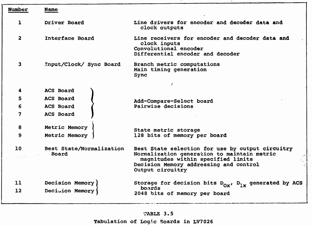
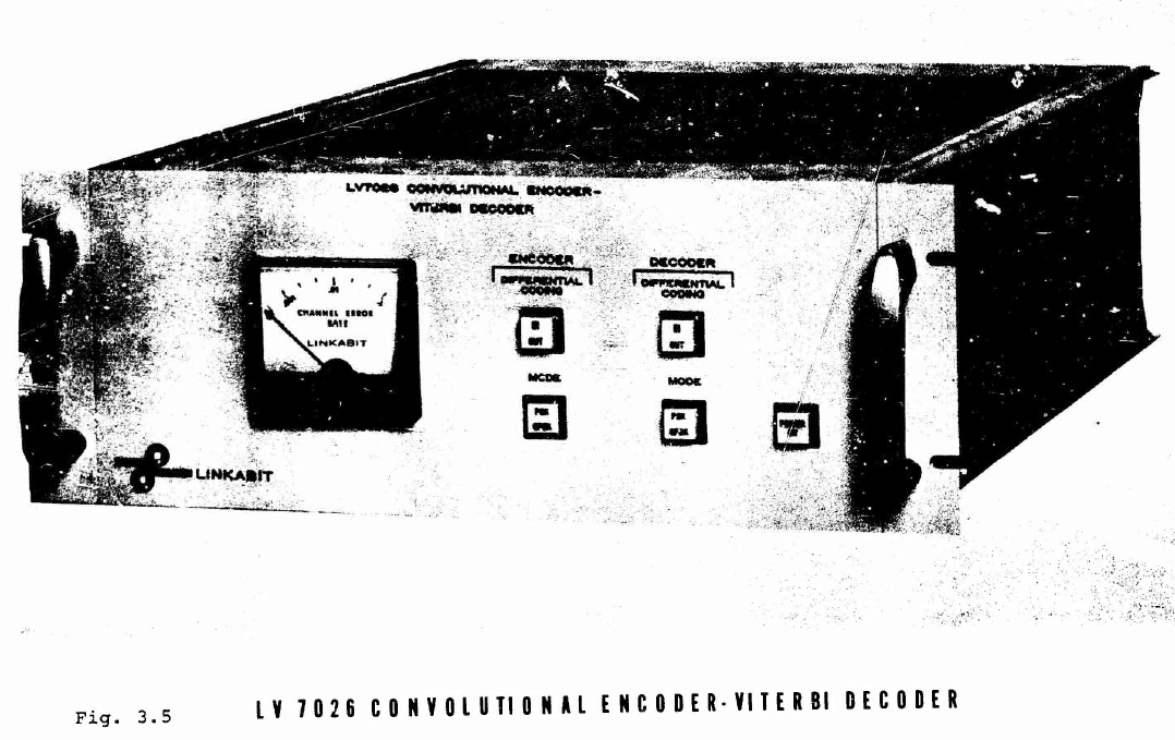
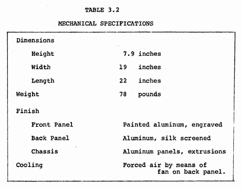
Though what's in the Voyager remains to be seen, the Performance Study of Viterbi Decoding as Related to Space Communications1 gives a description of such a system implemented on Earth for the ground station:

enter image description here

enter image description here

enter image description here

It is not the prototype, it is the final version.

The prototype may have required about 4 to 8 times the volume. Not a real monster, but filling a rack of half to full height. ( 32 to 64 inches height, 0.8 to 1.6 m)

The encoder for the spacecraft Voyager was a small and simple digital circuit, built with a 12 bit shift register and some logic.

The 12 bit shift register was built from 3 shift registers with 4 bit each requiring 3 DIL chips with 16 pins.

The logic was built with 6 half adders. One half adder needs two AND gates, one OR gate and one inverter. Each gate with two inputs. Using chips with 4 gates, we need three chips with And gates, two chips with OR gates and one chip with six inverters.

So we got only nine small DIP chips for the encoder.


1Linkabit Corporation, I. M Jacobs and J. A. Heller, August 31, 1971 Final technical report on Contract No. DAAB07-71-C-0148 (AD 738213)

$\endgroup$
9
  • $\begingroup$ Thanks! This system would be on the ground for receiving, was it also be used for transmitting? Presumably the encoder on the Voyagers was much smaller and built before launch, it will be great to find information on that as well. $\endgroup$
    – uhoh
    Commented Jul 10, 2021 at 8:23
  • 5
    $\begingroup$ @uhoh Even back in the 1970s / 1980s, encoding did not require "a big monster filling rack.” The Voyager spacecraft did not need "a big monster filling rack” to do the encoding. Encoding is orders of magnitude simpler than is decoding. That "big monster filling rack" was needed on the ground for decoding the Voyagers' high rate encoded downlink. Nowadays, a small FPGA will do the trick, but they didn't have those in the 1970s / 1980s. $\endgroup$ Commented Jul 10, 2021 at 14:57
  • 3
    $\begingroup$ @uhoh Another important distinction: The uplink to the Voyagers was incredibly small compared to the downlink from them. While the Voyagers had limited computation power, they had plenty of time to decode the uplink. If the uplink didn't decode properly, the vehicles could have asked for a redo. The Voyager spacecraft did not need a "big monster filling rack" for the decoding. $\endgroup$ Commented Jul 10, 2021 at 15:08
  • $\begingroup$ @DavidHammen Please check the wording of the question again. I've treated the hardware in Voyager separately from the hardware on the ground. I'm just encouraging Uwe to address the Voyager part now. $\endgroup$
    – uhoh
    Commented Jul 10, 2021 at 15:12
  • 1
    $\begingroup$ @DavidHammen I don't understand what it is that makes you think I don't appreciate that. There's nothing at all in the question that suggests that those things might be true. It simply does not appear that I don't recognize those things. The question is written to allow for an answer to be posted. There's absolutely nothing about Stack Exchange question writing that requires you to not know something in order to ask it. The question's function is to set up an answer. The answer's function is primarily for informing future readers. $\endgroup$
    – uhoh
    Commented Jul 10, 2021 at 15:23
1
$\begingroup$

The RS encoder is similar to Golay and Hamming encoders (shift-register based). For example, this resource gives a schematic diagram.

In principle, it is as "simple" as binary encoders (check bits calculated from info bits). The main difference (and complication) is that additions and multiplications now operate on bytes (check bytes calculated from info bytes), following special rules in exotic mathematical objects called "Galois fields". The set of 256 bytes forms a "field", a finite set in which you can have all the operations like with real numbers (additions, multiplications, divisions, logarithm,..), except that the results of these operations are confined to the finite set (Evariste Galois, a brilliant French mathematician introduced them in the 19th century. He died at the age of 21, in a duel). With enough memory, all these exotic operations could be pre-computed and stored in look-up tables.

RS encoders on Voyager spacecrafts are hardware-based since on-board computers at that time could not have enough memory for look-up tables (see Building the plane on the way up).

The RS code is usually used in combination with a Convolutional Code (CC). The combination is what is called a Concatenated Code. For details, CCSDS Telemetry Channel Coding (Historical).

$\endgroup$
8
  • $\begingroup$ The Golay encoder (one 24 bit word assigned to every 12 bit word in) wasn't a lookup table either? As such, it would require 4096 * 24 bits or about 12.3 kbytes. $\endgroup$
    – uhoh
    Commented Jul 12, 2021 at 10:14
  • $\begingroup$ @uhoh, the encoders of all BINARY codes (Golay, CC, Hamming, BCH,..) can be implemented with a few flipflops. So, probably they are HW-based too. What was challenging for NASA(JPL) engineers was the RS encoder. That's perhaps the reason why only Voyager 2 had the RS capability (please check). BTW, of the 24 bits of the Golay codeword, 12 bits are the info bits. So in a "brute-force" look-up table approach for Golay, you need 1/2 of your computed memory. $\endgroup$
    – Ng Ph
    Commented Jul 12, 2021 at 12:04
  • 1
    $\begingroup$ @uhoh, to be honest I have never implemented any code in FPGA to give you an exact number of flip-flops for a Golay encoder. The general takeaway is: it's a feedback shift register. You push your 12 bits of info in and (miracle!) the register contains your 11 check bits. Then add an overall parity bit. The codeword: 12 info bits + 11 Golay checks + 1 parity check. Take any pair of these codewords, they will differ by at least 8 positions. Take ANY 24-bit message, there will be 1 codeword that differs by at most 3 places => perfect sphere packing. $\endgroup$
    – Ng Ph
    Commented Jul 12, 2021 at 12:48
  • 1
    $\begingroup$ @uhoh, a mathematical miracle: Take the set of all 24-bit possibilities. Take the 4096 codewords of THE Golay code. Draw "spheres" of "Hamming distance" d=3 centered on each of these Golay codewords. These 4096 spheres fill-up the whole set. With Euclidian distance in a real space of dimension n, R^n, you can get such a result with n=1 only. With n=3, the best you can pack still leaves ~26% empty space (Kepler's conjecture, 1611, demonstrated formally in 1998) $\endgroup$
    – Ng Ph
    Commented Jul 12, 2021 at 13:08
  • 1
    $\begingroup$ @uhoh, a codeword has n=24 bits. It belongs to a "codebook", a subset of the n-dim "space". If your message has k info bits, you are allowed (n-k) check bits. For ex., a parity check code has a codebook 1/2 the size of the n-space (k=n-1), and any pair of codewords differ by at least 2 places. Any codebook such that any pair of codewords differs by at least (2t+1) places, can correct t errors. You also want your codebook to be as big as possible (=> pack the t-spheres). The order of info and check bits is up to you to choose (and agree with the Rx side). Usual convention is info bits first. $\endgroup$
    – Ng Ph
    Commented Jul 12, 2021 at 14:48

Your Answer

By clicking “Post Your Answer”, you agree to our terms of service and acknowledge you have read our privacy policy.

Not the answer you're looking for? Browse other questions tagged or ask your own question.