Tweeted twitter.com/StackSpaceExp/status/1066798839254917120
added 189 characters in body
Source Link
uhoh
  • 150.9k
  • 56
  • 505
  • 1.6k

I've been working on a design for a sounding rocket that can go to the Karman line, that I want to make my senior capstone project next year. As a part of this process, I am making a program to estimate the maximum altitude attained by the rocket and its going pretty well.

Here is the estimated flight for a 1000lbf engine with 120 lbs of total rocket and 80% fuel by weight: enter image description here
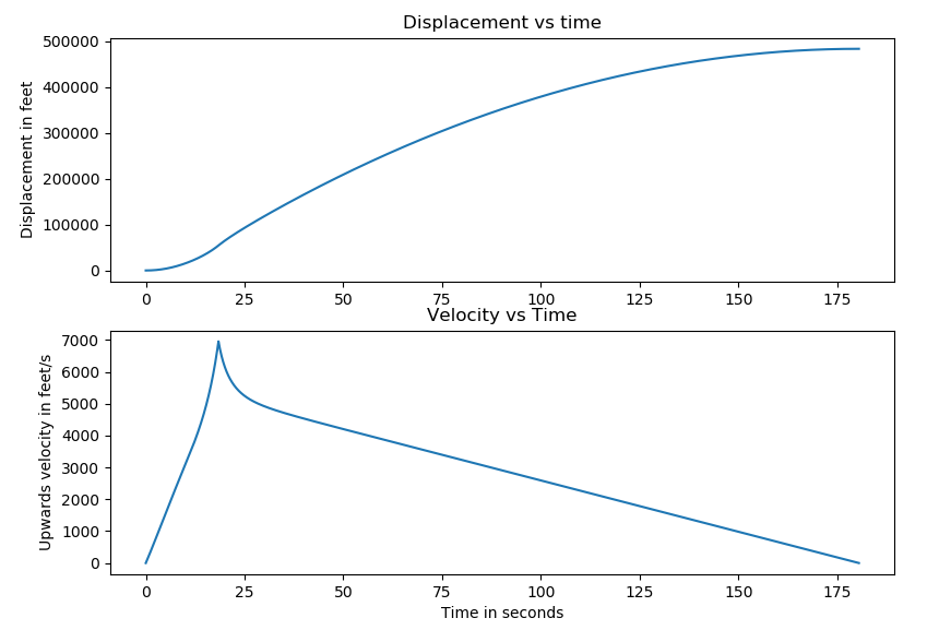
However, the current estimation I have is still a huuuuuge over estimation because it does not consider the effects of trans and supersonic flight on the coefficient of drag, which I imagine will have a dramatic impact on this code's output (notice the max velocity is 6800 ft/s...)

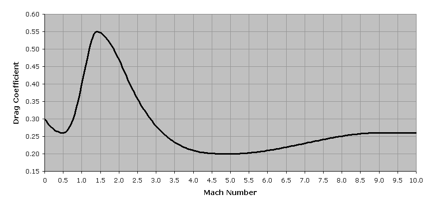
I was able to find this image relating atlas Cd to mach number here:

enter image description here

See this answer and way back machine for source.

How can I make a curve similar to this for our project? The rocket body is going to be a (ogive or parabolic probably) cone with a long cylindrical body and fins. I estimate that the Cd will be about .2-.25 at low speed flight.

How can I go about making a curve like this? How do I know at what mach number the pressure will be highest for my design? Should I change nose-cone shape to reduce drag at sonic speed? Are there any resources to guide me in the right direction here? Any advice would be greatly appreciated. We have access to a pretty slow wind tunnel and fluid dynamics software if that can help us any.

Thanks!
I've been working on a design for a sounding rocket that can go to the Karman line, that I want to make my senior capstone project next year. As a part of this process, I am making a program to estimate the maximum altitude attained by the rocket and its going pretty well.

Here is the estimated flight for a 1000lbf engine with 120 lbs of total rocket and 80% fuel by weight: enter image description here

However, the current estimation I have is still a huuuuuge over estimation because it does not consider the effects of trans and supersonic flight on the coefficient of drag, which I imagine will have a dramatic impact on this code's output (notice the max velocity is 6800 ft/s...)

I was able to find this image relating atlas Cd to mach number here:

enter image description here

See this answer and way back machine for source.

How can I make a curve similar to this for our project? The rocket body is going to be a (ogive or parabolic probably) cone with a long cylindrical body and fins. I estimate that the Cd will be about .2-.25 at low speed flight.

How can I go about making a curve like this? How do I know at what mach number the pressure will be highest for my design? Should I change nose-cone shape to reduce drag at sonic speed? Are there any resources to guide me in the right direction here? Any advice would be greatly appreciated. We have access to a pretty slow wind tunnel and fluid dynamics software if that can help us any.

Thanks!

added 109 characters in body
Source Link

I've been working on a design for a sounding rocket that can go to the Karman line, that I want to make my senior capstone project next year. As a part of this process, I am making a program to estimate the maximum altitude attained by the rocket and its going pretty well.

Here is the estimated flight for a 1000lbf engine with 120 lbs of total rocket and 80% fuel by weight: enter image description here

However, the current estimation I have is still a huuuuuge over estimation because it does not consider the effects of trans and supersonic flight on the coefficient of drag, which I imagine will have a dramatic impact on this code's output (notice the max velocity is 6800 ft/s...)

I was able to find this image relating atlas Cd to mach number here:

enter image description here

How can I make a curve similar to this for our project? The rocket body is going to be a (ogive or parabolic probably) cone with a long cylindrical body and fins. I estimate that the Cd will be about .2-.25 at low speed flight.

How can I go about making a curve like this? How do I know at what mach number the pressure will be highest for my design? Should I change nose-cone shape to reduce drag at sonic speed? Are there any resources to guide me in the right direction here? Any advice would be greatly appreciated. We have access to a pretty slow wind tunnel and fluid dynamics software if that can help us any.

Thanks!

I've been working on a design for a sounding rocket that can go to the Karman line, that I want to make my senior capstone project next year. As a part of this process, I am making a program to estimate the maximum altitude attained by the rocket and its going pretty well.

Here is the estimated flight for a 1000lbf engine with 120 lbs of total rocket and 80% fuel by weight: enter image description here

However, the current estimation I have is still a huuuuuge over estimation because it does not consider the effects of trans and supersonic flight on the coefficient of drag, which I imagine will have a dramatic impact on this code's output (notice the max velocity is 6800 ft/s...)

I was able to find this image relating atlas Cd to mach number here:

enter image description here

How can I make a curve similar to this for our project? The rocket body is going to be a (ogive or parabolic probably) cone with a long cylindrical body and fins. I estimate that the Cd will be about .2-.25 at low speed flight.

How can I go about making a curve like this? How do I know at what mach number the pressure will be highest for my design? Should I change nose-cone shape to reduce drag at sonic speed? Are there any resources to guide me in the right direction here? Any advice would be greatly appreciated.

I've been working on a design for a sounding rocket that can go to the Karman line, that I want to make my senior capstone project next year. As a part of this process, I am making a program to estimate the maximum altitude attained by the rocket and its going pretty well.

Here is the estimated flight for a 1000lbf engine with 120 lbs of total rocket and 80% fuel by weight: enter image description here

However, the current estimation I have is still a huuuuuge over estimation because it does not consider the effects of trans and supersonic flight on the coefficient of drag, which I imagine will have a dramatic impact on this code's output (notice the max velocity is 6800 ft/s...)

I was able to find this image relating atlas Cd to mach number here:

enter image description here

How can I make a curve similar to this for our project? The rocket body is going to be a (ogive or parabolic probably) cone with a long cylindrical body and fins. I estimate that the Cd will be about .2-.25 at low speed flight.

How can I go about making a curve like this? How do I know at what mach number the pressure will be highest for my design? Should I change nose-cone shape to reduce drag at sonic speed? Are there any resources to guide me in the right direction here? Any advice would be greatly appreciated. We have access to a pretty slow wind tunnel and fluid dynamics software if that can help us any.

Thanks!

Source Link

Understanding Coefficient of Drag Verses Mach Number for Launch Vehicles

I've been working on a design for a sounding rocket that can go to the Karman line, that I want to make my senior capstone project next year. As a part of this process, I am making a program to estimate the maximum altitude attained by the rocket and its going pretty well.

Here is the estimated flight for a 1000lbf engine with 120 lbs of total rocket and 80% fuel by weight: enter image description here

However, the current estimation I have is still a huuuuuge over estimation because it does not consider the effects of trans and supersonic flight on the coefficient of drag, which I imagine will have a dramatic impact on this code's output (notice the max velocity is 6800 ft/s...)

I was able to find this image relating atlas Cd to mach number here:

enter image description here

How can I make a curve similar to this for our project? The rocket body is going to be a (ogive or parabolic probably) cone with a long cylindrical body and fins. I estimate that the Cd will be about .2-.25 at low speed flight.

How can I go about making a curve like this? How do I know at what mach number the pressure will be highest for my design? Should I change nose-cone shape to reduce drag at sonic speed? Are there any resources to guide me in the right direction here? Any advice would be greatly appreciated.