1
$\begingroup$

edit: more photos of a model of Mariner 2 here at Historic Spacecraft's Mariner_2.

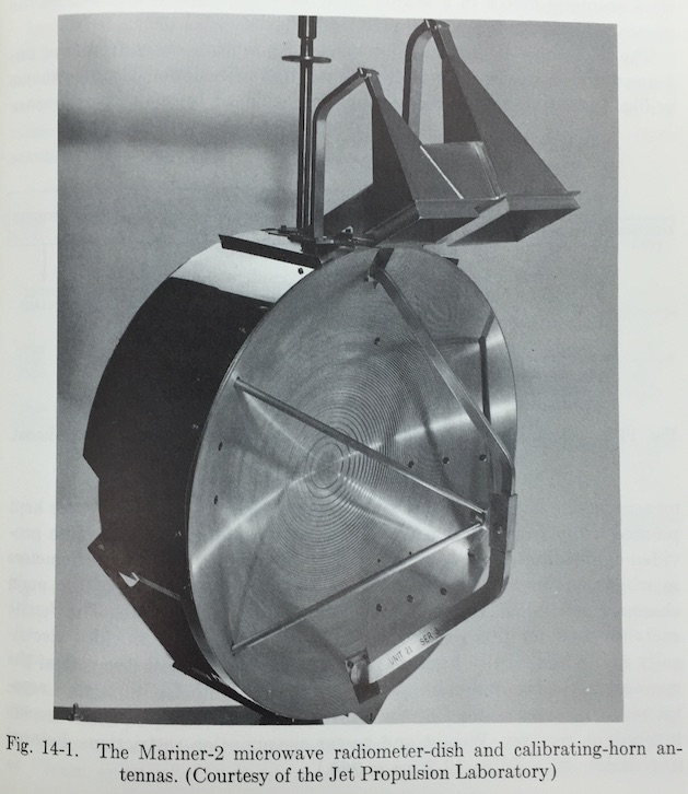
The images and quote are from the book Space Probes and Planetary Exploration William R. Corliss (written under the sponsorship of the National Aeronautics and Space Administration), Princeton, NJ: Van Nostrand, 1965.

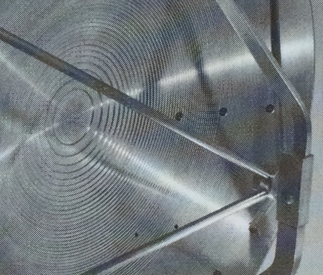
How exactly does this ridged surface "diffuse infrared radiation without defocusing the microwaves"? These are millimeter scale, with increasing pitch at larger radius, so I'm guessing that they contribute to the focusing of the microwaves.

I'd really prefer a supporting link that explains how these ridges work to maintain focus simultaneously on two different wavelengths I can guess how (19 and 13.5 mm are close to the ratio 3/2), but an official explanation would be much better!

A solid, aluminum, parabolic dish 48.5 cm in diameter was used on Mariner 2 (Fig. 14-1). Its field of view was 2.2° and 2.5° in half angle for the 13.5- and 19-mm channels, respectively. The ridged surface seen in the photograph diffuses infrared radiation without defocusing the microwaves. Infrared heating of the radiometer is minimized in this way. Ten hours prior to the Venus encounter, the whole dish was driven by a scanning motor in a search mode at 1°/sec. When the limb of the planet was acquired, the scan rate was reduced to 0.1°/sec.

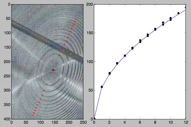
The first figure is a check that the radii do increase exactly as the square root of the ring number, which is what one might expect for a diffractive surface. The line is just 55 * sqrt(r) where r is in pixels.
enter image description here

enter image description here

enter image description here

$\endgroup$
2
  • 1
    $\begingroup$ Some really nice historical information and images; jpl.nasa.gov/mariner2 $\endgroup$
    – uhoh
    Commented Jan 18, 2018 at 4:47
  • $\begingroup$ It looks like a Fresnel reflector. Like a Fresnel lens, it works for different microwave wavelength. But if the surface is polished for microwaves and rough for infrared radiation, focusing will work only for longer microwave wavelength with specular reflection and not for shorter infrared wavelength with diffuse reflection, see. Like a matte paint for visible light on a polished surface or a etched surface of a glass panel. $\endgroup$
    – Uwe
    Commented Jan 18, 2018 at 16:50

2 Answers 2

3
$\begingroup$

Sorry, I have no documentation. I can only offer you a physics explanation.

The larger wavelength of the microwaves is too big to "see" the ridges. The wavefront is reflected by the general curve of the dish to arrive at the focus. The ridges are obviously much smaller than 13mm (assuming that's a 485mm diameter dish).

It's the same reason your microwave oven door shield can have holes in it. Since they're smaller than the wavelength, the energy is reflected efficiently. The ridges don't contribute to the focusing of the microwaves, they are ignored by the microwaves. As such, there's nothing special about how two different wavelengths are focused. Anything around that size or larger would be similarly focused.

The shorter-wavelength IR is affected by the ridges. The surfaces of the ridges do not focus to the same spot as the general curve. This reduces the IR power that reaches the parabolic focus.

$\endgroup$
5
  • $\begingroup$ That might work for roughness, but these concentric rings appear to increase in a precise, mathematically defined way. I'll add a plot to the question in a few minutes. A ridge only needs to be $\lambda / 4$ - just a few millimeters - to shift a wave by $\lambda / 2$ in reflection. I think there is something more than roughening going on here, in this particular case. $\endgroup$
    – uhoh
    Commented Jan 18, 2018 at 6:03
  • 3
    $\begingroup$ Rather than ridges cut into a smooth dish, I was just assuming the dish was made by larger-than-normal steps, cutting horizontal planes as the aluminum was turned on a lathe. If the steps are constant height, then making the overall shape a parabola would indeed be done by a mathematically decreasing distance between each step as you approach the edge. $\endgroup$
    – BowlOfRed
    Commented Jan 18, 2018 at 6:21
  • $\begingroup$ Indeed, the rings might simply be related to the manufacturing process. If the shape were generated by say a series of circles cut from a fixed thickness stock, it would make nearly the same pattern, see added plot in question. Hmm... interesting. Let's see if an authoritative reference emerges. $\endgroup$
    – uhoh
    Commented Jan 18, 2018 at 7:22
  • $\begingroup$ I found it! You might want to include statements from the first paragraph on page 52, and this link, into your answer. Click "Print this Article" on the following link to get the pdf: articles.adsabs.harvard.edu/full/1964AJ.....69...49B/… $\endgroup$
    – uhoh
    Commented Jan 18, 2018 at 23:09
  • $\begingroup$ Hi, are you interested in adding the paragraph I mentioned? I can make the edit if you are indisposed, or I can post it as an additional answer. Either way, I think it's important to have here somewhere. $\endgroup$
    – uhoh
    Commented Feb 2, 2018 at 7:12
0
$\begingroup$

tl;dr: @BowlOfRed's answer is correct. The steps are only about 2 mm tall. Compared to the shortest wavelength of 13.5 mm, that's only about 0.15 λ.


As I noted here, the 1966 paper Mariner 2 Microwave Radiometer Experiment and Results (The Astronomical Journal, 69, 1, pp. 49-58) Describes the system in detail and addresses this specifically. Clicking Print this article generates the pdf for you.

It can be noticed in Fig. 2 that the front surface of the paraboloid is of a stepped construction. The steps act as plane reflectors for infrared energy and thus avoid concentration of excessively high heat at the feed, should the instrument point at the sun during spacecraft maneuvers. The steps are small enough not to affect the microwave frequencies of interest, as proved by measurements of the antenna patterns.

The paper provides an in-depth discussion of the device's design and operation in space, including plenty of attention to calibration procedures during flight and data taking. It's quite an amazing instrument to build in the 1960's and fly to another planet and operate successfully there!


The effective diameter of the parabolic reflector used was 48.5 cm with a focal length of 19.3 cm. These values resulted in theoretical half-power beamwidths of 2.7 deg for Channel 1 and 2 deg for Channel 2, and gains of 35 and 38 dB, respectively.

With the focal length stated, we can now estimate the height of the steps.

For a parabola of focal length $f$ the shape of the curve is given by:

$$y(x) = \frac{x^2}{2 \ f} $$

With a radius of 242 mm and a focal length of 193mm, the depth of the dish is going to be roughly 150 mm. If the 10th ring is at (very!) roughly 170 pixels / 460 pixels as shown in the question, then there is going to be (also very!) roughly 75 rings total. The plot shows that the ring radius scales with the square root of radius which suggests that the heights of the steps are probably constant which makes sense.

150 / 75 yields an estimate of about 2 mm step height, and comparing this to the shorter wavelength of 13.5 mm suggest the step height is about 0.15 λ which is smaller than the canonical quarter-lambda number.

All of this just confirms that @BowlOfRed's answer is correct!

$\endgroup$

Your Answer

By clicking “Post Your Answer”, you agree to our terms of service and acknowledge you have read our privacy policy.

Not the answer you're looking for? Browse other questions tagged or ask your own question.