4
$\begingroup$

Cassini has quite a complex Radio Science Subsystem. Accorting to that article (and confirmed in Wikipedia):

Cassini is the only deep space mission to transmit to Earth at three radio wavelengths (approximately 14 cm wavelength, designated S-band; 4 cm, designated X-band; and 1 cm, designated Ka-band) simultaneously.

That says "simultaneously", quite a dish-full.

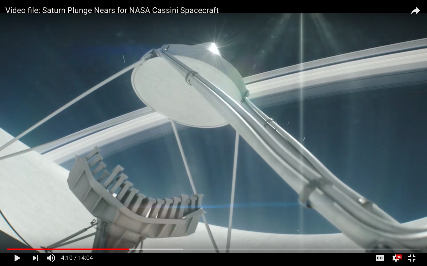
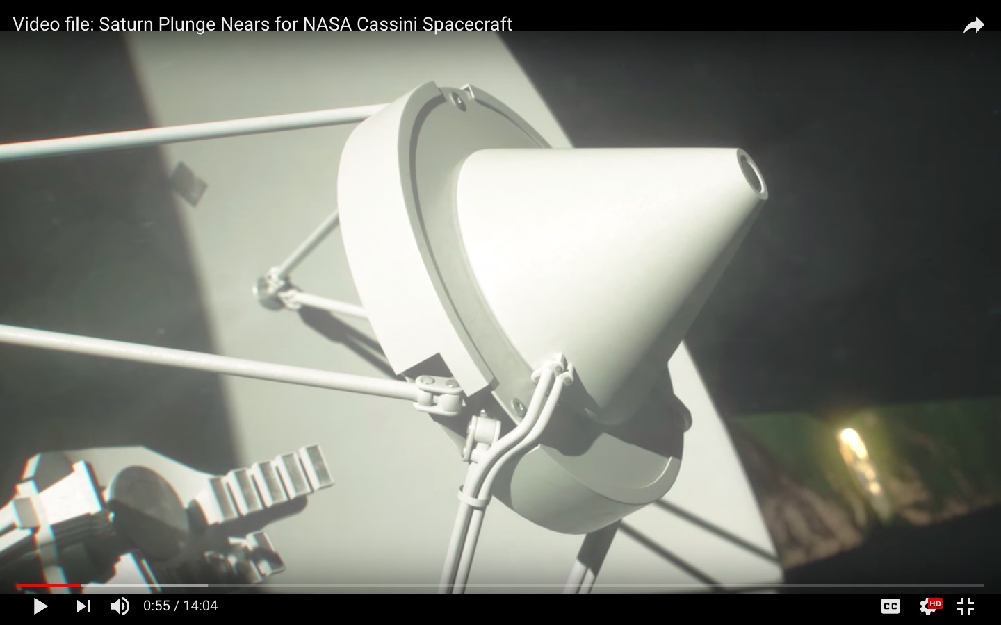
But there are also a bunch of non-axially located rectangular-waveguide-like objects that are also near the focus of the high-gain antenna system. What are these things for, and are they actually pointed towards the secondary mirror and using it for collimation? I am wondering if this gives some spatial resolution like a giant compound-eye of an insect.

below x2: Screen shots from the animated/simulated part of the montage video Video file: Saturn Plunge Nears for NASA Cassini Spacecraft found on the apparently official JPLraw YouTube channel. The video contains a variety of Cassini-related material, images, and interviews.

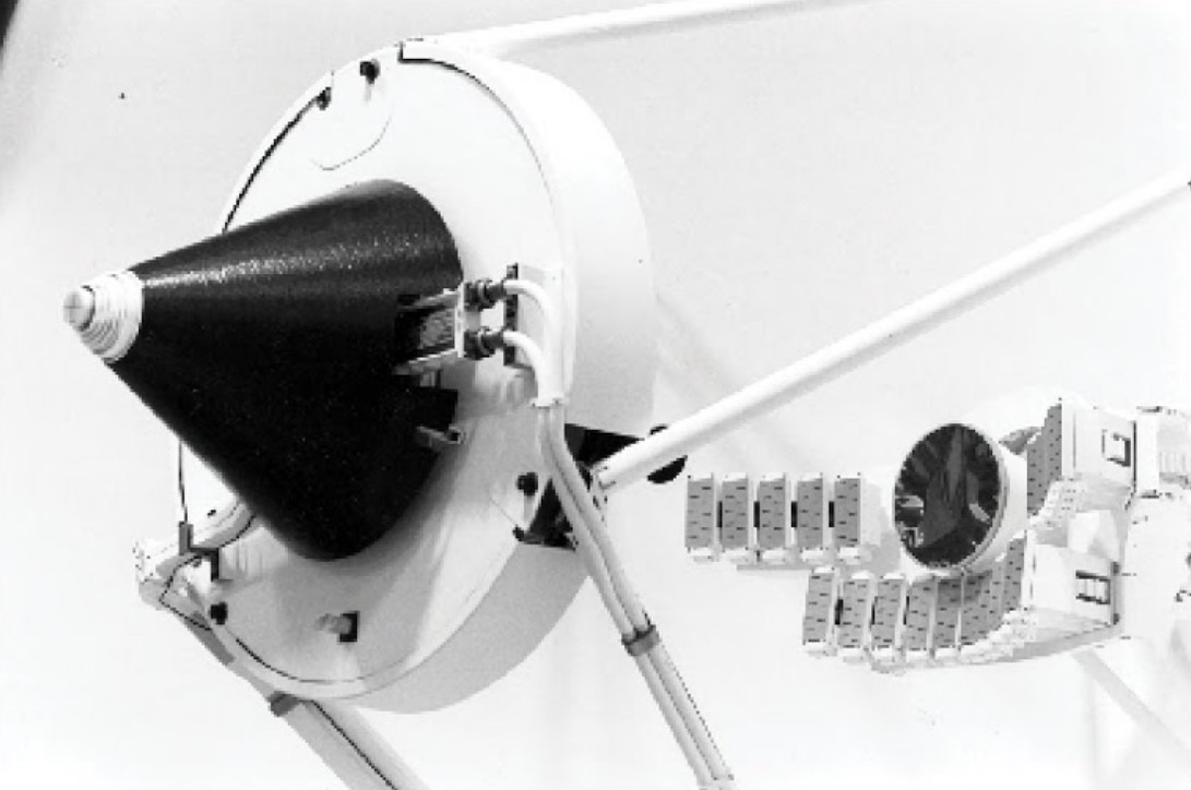
Cassini multiple waveguide feeds

Cassini multiple waveguide feeds and low-gain antenna

Cassini 2

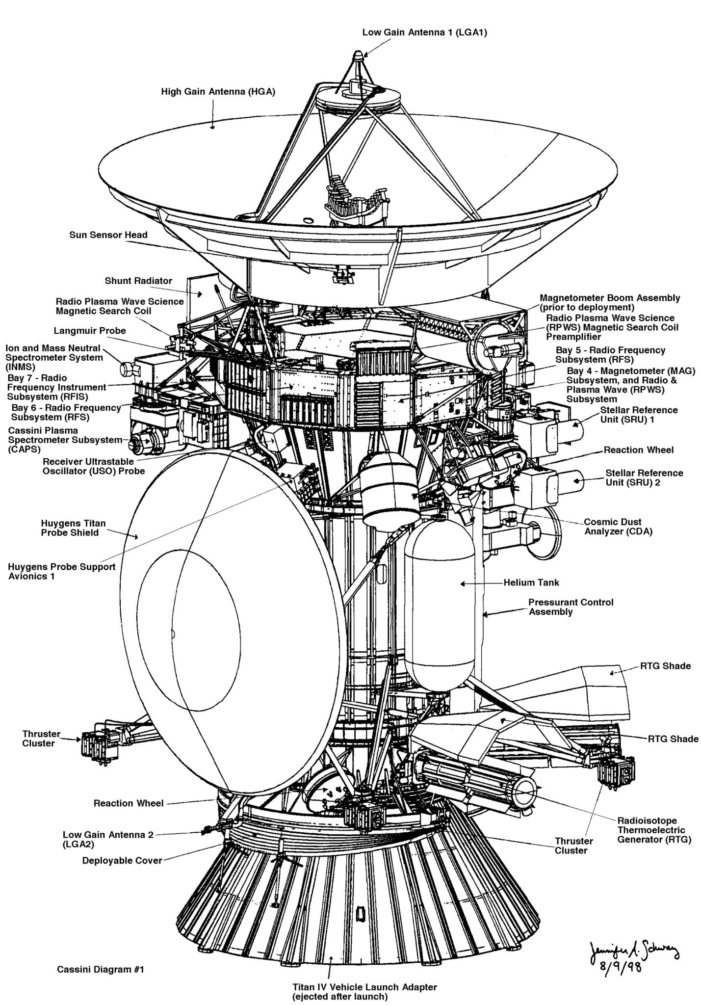
above: "A diagram of the Cassini spacecraft and Huygens probe." From here. NASA Jet Propulsion Laboratory. Open in a new window for full size so you can see the detail and read the descriptions!

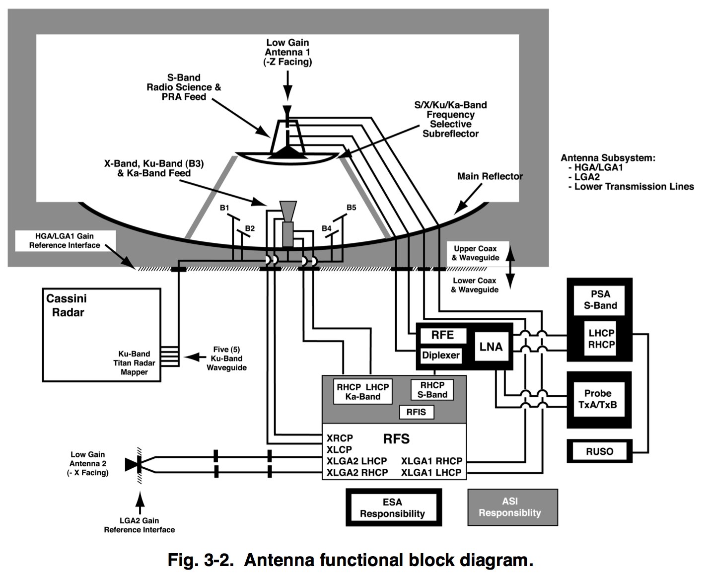
below: From Handbook of Reflector Antennas and Feed Systems Volume III: Applications of... edited by Sudhakar Rao, Lotfollah Shafai , Satish K. Sharma, screenshot from google books:
enter image description here

$\endgroup$
2
  • 1
    $\begingroup$ Speculation, but that looks to me like a beam-forming array so they can transmit off the boresight of the antenna. $\endgroup$
    – Tristan
    Commented Sep 14, 2017 at 18:05
  • $\begingroup$ @Tristan beam-forming is usually done with an array that's not also at the focal plane of an also-beam-forming Cassegrain reflector. This is optically more like a focal plane array - the Cassegrain system would form a different beam for each waveguide output. But that's just a working hypothesis. $\endgroup$
    – uhoh
    Commented Sep 14, 2017 at 18:22

1 Answer 1

5
$\begingroup$

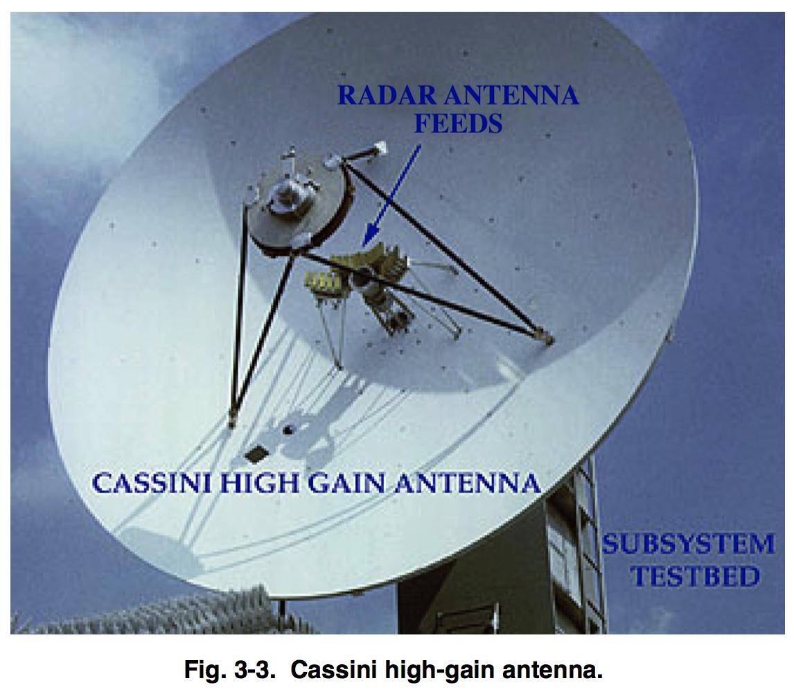
Some of those are the Ku-band antenna feeds for the Radar. The high-gain antenna also serves (served) as part of the Radar science instrument. The HGA was pointed at Titan many times to get synthetic-aperture radar images of the surface of Titan, otherwise obscured by the haze in the atmosphere to visible light instruments.

lots of feeds image of HGA

$\endgroup$
4
  • 4
    $\begingroup$ Buh bye Cassini, my first spacecraft. Sniff. $\endgroup$
    – Mark Adler
    Commented Sep 14, 2017 at 20:49
  • $\begingroup$ The real photo is much appreciated, thanks. I'm still scratching my head on the "Why are there so many..." part. Are these 20 or so rectangular windows mostly emitters, or receivers, or a mix of both? Are there so many in order to get some angular segmentation, as in a focal plane array? You may want to take a few days and reply later, the timing is awkward I know. $\endgroup$
    – uhoh
    Commented Sep 15, 2017 at 2:03
  • 1
    $\begingroup$ There are four look angles to the side and one on center for the radar. There are five horns for each of the four side look angles. $\endgroup$
    – Mark Adler
    Commented Sep 15, 2017 at 3:20
  • $\begingroup$ I've accepted the answer and I'll go off and do some more reading. I'm still having trouble understanding why five feed horns are used for a given look angle. Usually when using multiple phased emitters to produce a beam, they are in free space and not at the focal point of an imaging system. $\endgroup$
    – uhoh
    Commented Oct 10, 2017 at 15:52

Your Answer

By clicking “Post Your Answer”, you agree to our terms of service and acknowledge you have read our privacy policy.

Not the answer you're looking for? Browse other questions tagged or ask your own question.