2
$\begingroup$

I have seen an answer here how we can compute link budget in satellite communication.

Link Budget

$$ P_{RX} = P_{TX} + G_{TX} - L_{FS} + G_{RX} $$

  • $P_{RX}$: received power by spacecraft
  • $P_{TX}$: transmitted power by wristwatch
  • $G_{TX}$: Gain of wristwatch's transmitting antenna (compared to isotropic)
  • $L_{FS}$: Free space Loss, what we usually call $1/r^2$
  • $G_{RX}$: Gain of spacecraft's receiving antenna (compared to isotropic)

$$G \sim 20 \times \log_{10}\left( \frac{\pi d}{\lambda} \right)$$

$$L_{FS} = 20 \times \log_{10}\left( 4 \pi \frac{R}{\lambda} \right).$$

  1. Free space Loss component: If we compute it for Satellite-Ground link or for Intersatellite link, will the computation equation be the same?

In these two cases, we have two difference environment, and they should have different path losses.

  1. $$ P_{RX} = P_{TX} * G_{TX} * L_{FS} * G_{RX} * L_{atmosph} $$

in log scale

$$ P_{RX} = P_{TX} + G_{TX} + L_{FS} + G_{RX} + L_{atmosph} $$

  • Why $-L_{FS} $ is in the equation above?
  • Why does $L_{atmosph} $ skip?
$\endgroup$
2
  • 1
    $\begingroup$ Usually link budgets are not meant to be precise, they give a ballpark number to start with, then you can add various additional effects depending on your particular situation and need. In good weather for the lower "space bands" the atmospheric loss might only be a few dB. But in bad weather, it can go up substantially both due to absorption of precipitable water vapor, and due to scattering by precipitation (snow, ice, rain drops). $\endgroup$
    – uhoh
    Commented Nov 22, 2021 at 12:57
  • $\begingroup$ Have a look at the plot in this answer to What is the highest non-optical frequency used or tested for use in deep space communication? For optical communications even normal clouds will completely block laser line-of-sight links. So the link budget expression you've linked to in my answer is for X-band and Ka-band, and in good to slightly rainy weather. $\endgroup$
    – uhoh
    Commented Nov 22, 2021 at 12:57

3 Answers 3

4
$\begingroup$

Why -$L_{FS}$ is in the equation above?

The minus sign is more of a readability convention as far as I know: gains and losses are both given as positive numbers in dB, and then gains are added (in log scale) and losses subtracted (in log scale).

It is equally correct to give losses as a negative number in dB and add all gains and losses (like in the second equation. It should be clear from context which convention is used.

$\endgroup$
2
$\begingroup$

Usually link budgets are not meant to be precise, they give a ballpark number to start with, then you can add various additional effects depending on your particular situation and need. See for example:

$$P_{rx }= P_{tx }+ G_{tx } + G_{rx} + L_{range} + h_{tx } + h_{atm} + h_{rx } + T_{point} + R_{point}$$

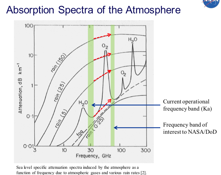
In good weather for the lower "space bands" the atmospheric loss might only be a few dB. But in bad weather, it can go up substantially both due to absorption of precipitable water vapor

and due to scattering by precipitation (snow, ice, rain drops).

Have a look at the plot in @BobJacobsen's answer to What is the highest non-optical frequency used or tested for use in deep space communication? For optical communications even normal clouds will completely block laser line-of-sight links. So the link budget expression you've linked to in my answer is for X-band and Ka-band, and in good to slightly rainy weather.


enter image description here

$\endgroup$
1
  • 1
    $\begingroup$ the first your linked question: How to compute pointing loss? I have found here the eqaution (p 13) link. I need to compute the pointing accuracy, as i understood it is an angle in radians, isnt? What is its equation? $\endgroup$
    – user176070
    Commented Nov 23, 2021 at 8:07
1
$\begingroup$

For pointing loss, take a look at my answer to a link budget question, which I am amused to note contains a graph I made which is nearly identical to Figure 8.2 of Carrasco-Casado and Mata-Calvo that you linked.

Maximum gain, the highest concentration of power you can obtain, is achieved with each antenna pointed directly into the center of the other. Pointing loss is any deviation from that maximum, due to one or both of the antennas not being located at the peak of the pattern of the other antenna. That can be because

  • you don't know exactly where one of the antennas is, so you're searching for it by moving the other around
  • you are trying to collect more than one signal at a time, so you chose a compromise pointing that wouldn't give one a massive advantage over the others
  • there is a powerful interferer in the field of view, and you decided to improve the signal-to-noise ratio (SNR) by pointing the antenna away from the real target in a way that drops a null right on top of the interferer
  • the remote antenna is on a spacecraft, and you misunderstand where it is pointing, perhaps because of an error made while interpreting your telemetry, or some on-board failure
  • your control over one or both of the antennas is only coarse (perhaps a subcontractor made a control interface which only accepts angles of integer degrees)
  • there are other constraints that prevent you from pointing the antenna optimally, or from knowing exactly where it is pointed.

For every aperture type, there is a corresponding formula for how much loss in decibels you suffer for a given error in pointing angle. This is exactly what the $10\log_{10}(4J_1^2(x)/x^2)$ plot I mentioned above does, for a uniformly illuminated circular aperture. For a different antenna shape or weighting, you need to use a different curve, which may be purely empirical (measured, not calculated).

The exact number of radians by which your pointing is not centered, however, is not something that can be calculated, or at least not without detailed knowledge of the situation. You need to understand the model you are using, or have some statistics about how well pointing has worked in the past, or some other outside source of information about what typical means in your specific situation. The way it is generally used in practice is for antenna shape $X$, a pointing angle error $Y$ costs us $Z$ decibels of link margin, so with the current design we're okay as long as $Y<Q$.
$\endgroup$

Your Answer

By clicking “Post Your Answer”, you agree to our terms of service and acknowledge you have read our privacy policy.

Not the answer you're looking for? Browse other questions tagged or ask your own question.