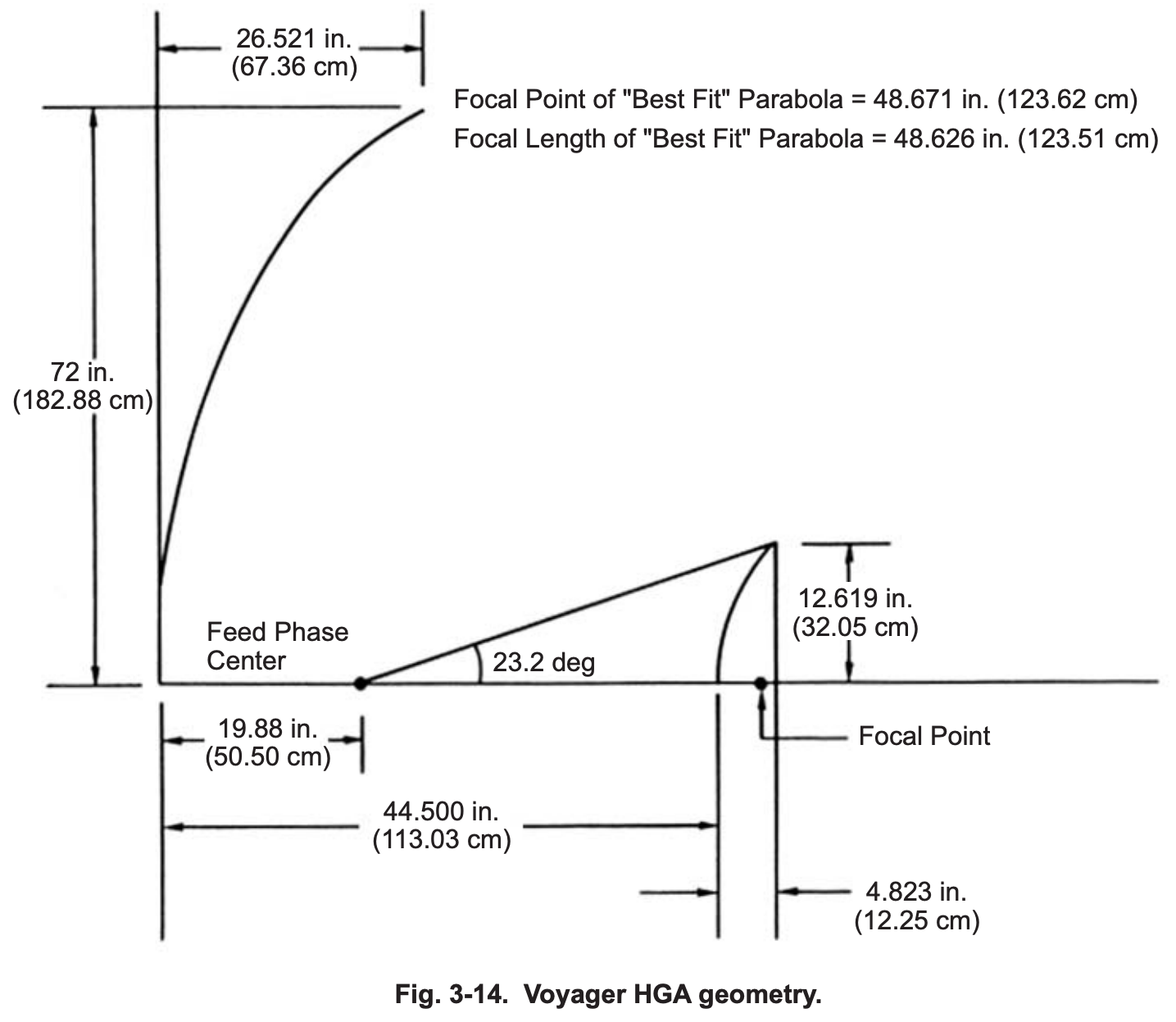
tl;dr: From Fig. 3.14 below:
- Focal Point of "Best Fit" Parabola = 48.671 in. (123.62 cm)
- Focal Length of "Best Fit" Parabola = 48.626 in. (123.51 cm)
And:
- "The antennas used on the Voyager, Galileo, and
Cassini spacecraft described in Chapter 5 were all dual-shaped systems."
Further reading:
While the Voyagers' primary reflector is very close to a parabola, they've slightly tweaked the shape as part of the design of the secondary reflector (it's a Cassegrain-like antenna for the X-band system.)
And the secondary reflector is optimized to minimize spillover and fill the aperture as uniformly as possible. I think what those mean exactly and why they were important will make excellent followup questions!
Here are some drawings and text from Chapter 3 of the Descanso volume 8 publication Spaceborne Antennas for Planetary Exploration, William A. Imbriale, Editor
Also see Sections 1.2.2 through 1.2.4 for some more mathematical background.


3.2.2 Requirements
The HGA consists of a paraboloidal reflector with a 3.66-m (12-ft.)
diameter circular aperture and suitable S- and X-band feeds. The X-band feed
utilizes dual shaped Cassegrain optics, and the S-band feed utilizes a prime
focus feed. A frequency selective subreflector (FSS) reflects the X-band signal
and passes the S-band signal. The HGA has a focal length to diameter (F/D)
ratio of 0.338. The HGA is RHCP and operates over the frequency ranges of 2115 ±5 and 2295 ±5 MHz. It also operates over the frequency range of 8422
±20 MHz, with a dual polarized feed that yields a right-hand or left-hand
circularly polarized wave from the HGA depending on which of its input ports
is excited by the RFS. S-band signals are received by the HGA at 2115 ±5 MHz
and routed to the RFS receiver. S-band signals at 2295 ±5 MHz from the RFS S-band transmitter are radiated via the HGA. X-band signals at 8422 ±20 MHz
from the RFS X-band transmitter are radiated via the HGA.
The LGA radiates a circularly polarized, broadbeam pattern directly to
Earth. The LGA requirements are summarized in Table 3-1.
3.2.3 Voyager High-Gain Antenna
Since a 3.66-m reflector was the largest solid reflector diameter that could
fit into the nose cone fairing without deployment, it was desirable to have the
highest aperture efficiency possible. A high-efficiency dual-reflector system
generally requires that (1) most of the feed energy be intercepted by the reflectors (i.e., low spillover), and (2) the field in the aperture of the main reflector be
distributed as uniformly as possible. Ordinarily, reduction of spillover requires
tapering the aperture distribution, and a uniform aperture distribution generally
involves substantial spillover. Consequently, optimum performance
traditionally involves a compromise that has limited efficiencies of
conventional systems to about 55–60 percent. The shaped dual-reflector
concept permits the apparent contradiction between the two requirements for
high efficiency to be overcome with the following rationale: a feed is selected
with a high taper at the edge of the subreflector to minimize forward spillover;
the subreflector profile is designed to distribute the highly tapered energy
uniformly over the aperture of the main reflector. By designing for constant
aperture illumination (see Section 1.2.4), the classical hyperboloid subreflector
is transformed into an empirical contour with a smaller radius of curvature than
a hyperboloid in the central section to deflect more of the rays to the outer part
of the main reflector. Thus, there is little spillover and, at the same time, a
nearly uniform aperture distribution. The main reflector must then be slightly reshaped from its original paraboloidal contour to produce a constant-phase distribution
The HGA was dual-shaped for optimum efficiency at X-band (see
Fig. 3-14). The dichroic subreflector is transparent to radiation from an S-band
prime-focus horn nestled behind it. At S-band, the main reflector differs little
from a paraboloid. The focus of the resultant best-fit paraboloid was chosen as
the prime focus for the S-band feed.

