13
$\begingroup$

While watching a launch of an Atlas V, I couldn't help but notice that the boosters were positioned asymmetrically. There was one booster on one side of the rocket, and two boosters on the other side.

Further research revealed that the positioning for the booster was intentional. Which is odd, because off-setting the boosters will give more thrust to one side of the rocket, and in turn, end in a disaster!

But that didn't happen during the launch. The rocket managed to fly perfectly upwards! How did they manage to do that? Why did they even position the boosters that way! Does it hold some sort of benefit? And if so, why don't people use that more and more often?

$\endgroup$
1

3 Answers 3

13
$\begingroup$

The nozzles of the SRBs are canted outward, so the line of thrust from each SRB passes close to the center of mass of the rocket, so that the net torque from asymmetrical booster arrangements is minimized. The main engine on the Atlas, as with most orbital launchers, is gimballed such that it can direct thrust to offset any remaining imbalanced thrust from the boosters (or any other disturbance).

Atlas uses only as many boosters as it needs for a given payload -- from zero to 5 -- and some of those configurations are asymmetrical. It looks especially odd using only a single booster, as in this video:

The fundamental reason for the asymmetry seems to be the orientation of the paired nozzles of the core engine, combined with the positioning of the LOX feed line running along the outside side of the first-stage tank.

$\endgroup$
2
  • $\begingroup$ Thanks, that clearly answers the "how" part of the question. For the "why", "what benefit" and "why not more often" parts of the question" its still not clear though. Whilst its unavoidable with a one booster configuration there is still a choice with the three booster case to mount them symmetrically. It seems hard to imagine in a non-reusable stage that the extra losses from flying sideways don't out-weigh the design effort to check out slightly different booster attachment points. Is this really the case? $\endgroup$
    – Puffin
    Commented Oct 11, 2016 at 6:29
  • 3
    $\begingroup$ According to this Reddit post, the asymmetry is driven by the orientation of the paired nozzles in the main engine versus the location of the LOX feed line running down the outside of the fuel tank: m.reddit.com/r/spaceflight/comments/3d3a7u/… $\endgroup$ Commented Oct 11, 2016 at 8:52
9
$\begingroup$

There are tradeoffs at work here. The current configuration allows them to use one first stage design for 1-5 boosters. A first stage that has symmetric attachment points, needs 2+4+4 = 10 attachment points for the 2, 3, 4, and 5 booster cases.

Another approach would be to discard the odd numbered configurations altogether and go to 2, 4, 6, 8 boosters. That means a higher manufacturing cost and more dead weight (more attachment points, less efficient boosters).

In both cases there's a tradeoff between manufacturing cost and complexity, and rocket efficiency (performance loss due to non-optimal configurations). Apparently the tradeoff was favorable for the current 1-5 booster configuration.

The Atlas V first stage is built to in a single configuration. Here's the first stage for OSIRIS-REx, an Atlas V 441 launch with one booster attached. I've indicated attachment points for 2 boosters, indicating they will fly with unused attachment points.
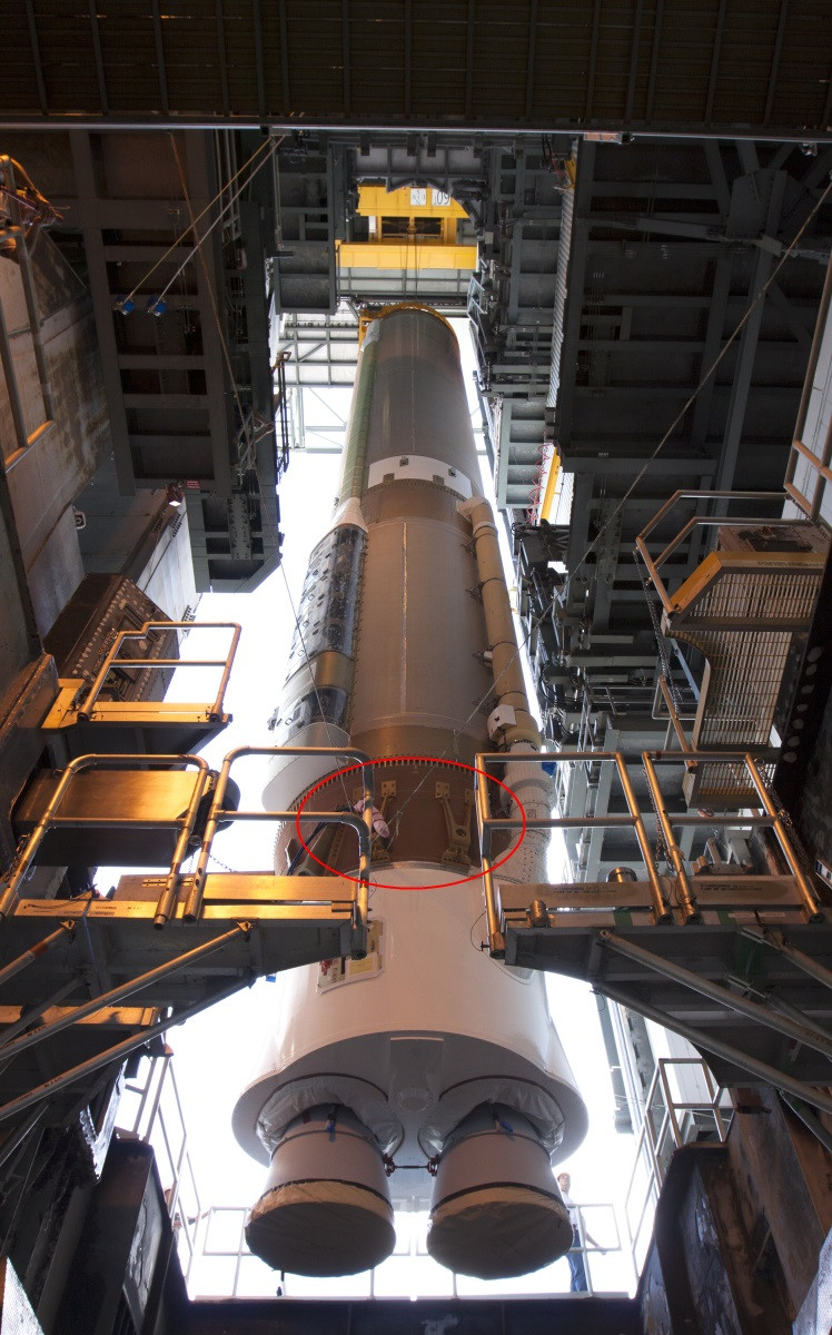
Atlas V 441

This photo also shows there's lots of places around the circumference of the stage where you can't attach boosters due to LOX lines or electronics attached to the outside. This is why e.g. the 4-booster variant is asymmetrical. Apparently, the Common Core Booster was not initially designed to be used with solid boosters, and when they had to be added later they didn't want to rearrange the rest of the stage.

Being designed for government contracts in an era with very little competition, it's feasible they didn't want to spend money wringing out the last bit of performance from the design.

$\endgroup$
6
  • 1
    $\begingroup$ This is getting closer to the heart of it, but assumes that unused attachment points are dead-weight (why carry them at all, you can be certain the design is not fixed, flight to flight). I still find it hard to believe that the extra design effort involved in not flying unused hardware would out-weigh the penalty of flying with a sideways drift. I'm beginning to think this could simply be the penalty of large organisations, the design that makes it to flight is in no way any kind of optimum in the trade-off that you describe. $\endgroup$
    – Puffin
    Commented Oct 12, 2016 at 10:43
  • 2
    $\begingroup$ Hard to believe, but it really happens. See the photo I've added. $\endgroup$
    – Hobbes
    Commented Oct 12, 2016 at 11:54
  • 1
    $\begingroup$ Understood, but my point was about the trade between flying diagonally with respect to the cylindrical long axis versus the effort of putting the attachment points such as to make vehicle more symmetrical. $\endgroup$
    – Puffin
    Commented Oct 12, 2016 at 15:20
  • 1
    $\begingroup$ Hm.. So how do they counteract the extra thrust produced by one of the boosters? $\endgroup$
    – Frank
    Commented Oct 12, 2016 at 17:16
  • 2
    $\begingroup$ By gimbaling the first stage engine. $\endgroup$
    – Hobbes
    Commented Oct 12, 2016 at 17:19
5
$\begingroup$

The Delta rocket started out with separate versions of the aft end for different numbers solid rocket boosters attached. Eventually McDonnell Douglas standardized, introducing the Universal Boattail Thor (UBT) with with a full complement of nine attach points regardless of how many solid boosters were to be flown on a mission. The positions for the boosters were not evenly spaced on the UBT, though unlike for some Atlas V configurations the aggregate thrust was always symmetrical.

As I'm sure was the case with Atlas V, MDAC's decision to use the same aft end regardless of the number of solid boosters flown on a mission was founded in engineering analysis which traded performance increments against program cost increments, and took consideration of reliability intangibles such as that the more versions of something you fly, the more chance for problems and the less flights each version gets compared to if there is just a single one... diminishing the demonstrated reliability for any of the various configurations relative to only a single type.

Finally, it appears from inspection (i.e. I don't specifically know, but I do have a structural engineering background) that these "attach fittings" are structural elements which carry loads for the frustum. That would allow the frustum and associated internal structure to be made lighter, so the attach fittings would thus not be deadweight even if no booster is present at a given position. More like that they are external "ribs", which then do double-duty when there is a booster attached.

$\endgroup$
4
  • $\begingroup$ Interesting. Do you have a reference where we can read more about this? $\endgroup$
    – Hobbes
    Commented Jan 21, 2018 at 13:30
  • $\begingroup$ I'm mostly working from internal MDAC documents and drawings, such as "Castor Solid Motor Attachment Configurations", which for the 9-motor arrangement shows 34 degree angles between the centerlines of each of the three paired groups, and 43 degrees between the centerlines of any of the three unpaired motors and an adjacent paired motor. $\endgroup$ Commented Jan 22, 2018 at 16:53
  • $\begingroup$ Note that by the time of the Delta II, the spacing of the solid motors was again even [Ref: "Rockets of the World", Peter Alway]. In between the original UBT and the Delta II, the later-version Castors on the "Straight 8" Deltas were closer to even than originally: 38.8 deg and 40.6 deg substituted in my earlier description [Ref: First Stage with Castor IV Solid Motors DSV-3P-11C, MDAC internal document] $\endgroup$ Commented Jan 22, 2018 at 17:08
  • $\begingroup$ Introduction of the UBT is mentioned in "The Delta Launch Vehicle Past Present and Future" MDC G8770 Table I (Year: 1972 / Delta Model: 903). Around that time Av Week also ran an article on MDAC's move to the UBT -- sorry I couldn't find my copy to provide the specific date. $\endgroup$ Commented Jan 22, 2018 at 17:09

Your Answer

By clicking “Post Your Answer”, you agree to our terms of service and acknowledge you have read our privacy policy.

Not the answer you're looking for? Browse other questions tagged or ask your own question.