First, ignore what Wikipedia claims about attitude indicators. It shows a diagram of the inside of an airplane attitude indicator. I am not inlining this image because -- although some airplanes may use such an indicator -- it is completely wrong about spacecraft attitude indicators.
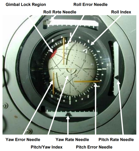
Let's look at what is displayed on a spacecraft attitude indicator. The ball itself only displays two axes: pitch and yaw. Roll is displayed by a triangular "roll index" marker that moves around the circumference of the display; it is not on the ball itself. The angular velocity around each axis is displayed by three "rate needle" meters around the perimeter of the instrument: pitch to the right of the ball, yaw below the ball, and roll above the ball. When there is a target to reach, three orange-yellow "error needles" show the error between the desired and actual angles in each of the three axes.

Gemini, Apollo, and the Space Shuttle used gyroscopes to measure the spacecraft orientation. (For redundancy, there was more than one gyro.) However, it is important to understand that these gyros were completely separate devices external to the attitude indicator. There is no spinning gyroscope inside the ball of a spacecraft attitude indicator.
The gyros in the Apollo CM and LM output analog signals that represented the gimbal angles of these gyros. These are the gimbals that were susceptible to "gimbal lock". The analog signals of the gyros were displayed on some meters below the attitude indicator, and also fed into two automated systems:
The Stabilization and Control System was an analog system that could perform basic attitude maneuvers in case the computer failed. There were thumbwheel switches where the pilot could dial in a pitch, yaw, and roll; the SCS could compare these settings to the gyro outputs and automatically turn the spacecraft to the desired attitude. The SCS also calculated the angular velocities from the gyro outputs, which were then sent to the "rate needles" on the attitude indicator. There was another control mode where the pilot could set an angular velocity for a desired axis, and the SCS would activate the RCS thrusters to turn the spacecraft at that speed on that axis, and stop motion on all of the other axes. This mode was used for the "barbecue roll" and also to terminate all rotation.
The Apollo Guidance Computer was a digital system that was much more capable that the SCS. Programs could calibrate the gyros from star positions, convert the gyro angles to other coordinate systems, and execute main engine burns in combination with attitude corrections.
The pilot could use a rotary switch to choose between which coordinate system to show on the attitude indicator: the raw gyro angles, or the coordinate system converted by the computer. The output of this switch was three analog signals (pitch, yaw, roll) to the attitude indicator.
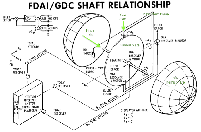
Inside the attitude indicator are three servo mechanisms. A sensor measures the angle of an axle, which is compared to the analog signal. The error between the two drives a motor which spins the axle to the intended angle:
Spacecraft orientation with respect to a selected inertial reference frame is also displayed on the attitude indicator ball. This display contains three servo control loops that are used to rotate the ball about three independent axes.

The roll servo turns the ring around the circumference of the display.
The yaw servo is affixed to the frame of the attitude indicator, turning a vertical axle. In the middle of this axle is a gimbal plate, and the pitch servo is attached to that. Electrical connections to the pitch servo must pass through slip rings on the yaw axle:

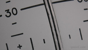
The pitch servo turns an axle with the two hemispherical shells of the indicator ball. There is a gap between the two hemispheres; this is necessary for the yaw axle to clear. You can see the gap here:

Because there is only one gimbal, and because slip rings are used for the inner connections, the attitude indicator is not capable of gimbal lock. The ball can turn any number and combination of turns in the yaw and pitch axes without binding up. Gimbal lock was an issue with the gyroscopes, not the attitude indicators. However, a red region corresponding to the gyro gimbal lock was painted on the ball.
Prior to the MEDS makeover, the Shuttle simulators used refurbished Apollo attitude indicators (compare Apollo and Shuttle). The electronics and much of the mechanicals were redone, allowing the ball to roll with the roll index. Because the Shuttle's gyros were not susceptible to gimbal lock, the red region was painted over:
Also note remnants of the roll gimbal lock red warning zone between the 255 and 285 degree index lines, which has also been painted over in black.


