Update 2
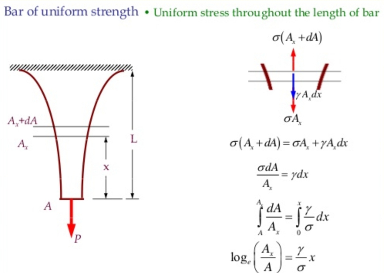
The taper ratio formula seems to be correct. The crosscheck stress calculation error mentioned in the Update 1 below is found to be due to:
a) incorrectly calculated tether volume (and therefore mass). I assumed a linear change of cross section area across the tether length. In fact, to achieve the uniform strength, a logarithmic increase in erea is required.

b) not accounting for varying gravity across the altitude (from 8.87001 m/s2 at the surface to 8.72529 m/s2 at 50 km altitude).
The tether mass values are now corrected in the text of the Update 1 below.
In this answer I will try to summarize practical challenges of the basalt fiber tether from mechanical point of view (i.e. assuming questions of what the aerostat is and how it's placed in its designated point are already solved), some of which are already mentioned in the comments to the question.
Deviations from theoretical mechanical strength.
According to article "Natural and man-made fibers: Physical and mechanical properties" by
M. De Araújo, Fibrous and Composite Materials for Civil Engineering Applications, 2011:
The manufacture of basalt fibre requires the melting of the quarried basalt rock to about 1400 °C, this is then extruded through small nozzles to produce continuous filaments of basalt fibre.
Imperfections are virtually impossible to avoid in practical manufacturing of any type of construction materials.
Some of the manufacturing challenges can be found in the article "Basalt Fibres" by Boris Mahltig, Inorganic and Composite Fibers, 2018, among them are possible inhomogenities of the natural basalt stones (the raw material) and problems with the non-homogeneous formation of material structure (and therefore worsened and non-reproducible mechanical properties) during cooling (solidification) phase.
Achieving uniform taper. 50km of continuous wire is a very large length; I'm not quite sure that achieving uniform taper over this length is even possible. In order to achieve this, the orifice through which the molten basalt is extruded has to increase in controllable and continuous manner from 1.128 mm to 2.044 mm at a rate of 0.018 micrometers per 1m of the tether.
Minimum bending radius for winding onto a reel.
Having elasticity modulus of ~85 GPa, basalt wire is surprisingly flexible:
From formulas in this page, we can calculate the bending radius as
R=(E/S)*y,
Where E is elasticity modulus, S is stress and y is the wire cross-section radius.
Let's assume safety factor of 10 (by allowing stress to be 10 times less than ultimate tensile stress of 3 GPa), then:
R=(85/0.3)*1.022=289.6 mm, which is not too small, but quite achievable.
The spring effect of the wound wire might be a practical problem though, in which case the reel diameter needs to be increased.
Speed of winding/unwinding needs to be slow enough to not heat up the parts of guiding mechanism which are in direct contact with the wire. (I assume some sort of guiding mechanism has to be involved in order to guide the wire as it winds on the reel through its width, otherwise 50 km of the wire will end up extremely messy on the reel)
Uniformity of layers on the reel. It would be practically hard to neatly guide the winding of such a small (and tapering) diameter. This will result in local contact stresses and local bending over underlying wires with much smaller local radius, hence larger stresses.
Fatigue and Fracture toughness. Over numerous cycles of winding/unwinding micro cracks may occur and propagate. I don't know how basalt performs specifically, but brittle materials overall are not very resilient to fatigue and have low fracture toughness.
Safety factor of 3 is a bit on a low side for an elevator application. Typically it's within the range of 3 to 6 for cranes, 8 to 13 for cargo elevators, and 9 to 25 for human-rated elevators. An additional coefficient for dynamic loads also better to be included.
This means larger and heavier tether.
Single wire vs rope. Any fracture of a solid material (whether it's fatigue, static or rapid dynamic load) always starts and develops from an imperfection in material structure. Once the crack is initiated, it takes a little effort to propagate through the whole cross-section. Once that happens, your elevator is gone.
This is the reason why a rope, or in case of metallic materials wire rope (woven from multiple wires of smaller diameter) is used instead in such Earthly applications as suspension bridges, guide wires to support towers, aerial tramways and lifts/elevators/cranes: if a single wire ruptures, the rest of the bundle still can handle the load. Elevators though use another advantage of wire rope: being made from steel it can flex and be wound easily, unlike a single bar of equivalent section.
For our basalt tether using rope made of woven smaller fibers of equivalent strength would mean a slightly larger diameter, hence a larger reel. It would be easier to bend (less spring action) and perhaps more practical to achieve the taper.
Frankly speaking, I can't think of any practical application where a single flexible wire made of brittle material is used to hold/support a load.
The last in this list, but not least important, the terminations

Picture borrowed from here
Steel is ductile, hence can be bent around a small radius for terminations. Basalt rope might be OK, but a single basalt wire would require quite a large radius.
Swage sleeves or clamps are using compression to fix the end of the single wire or rope. Again, local non-uniformity of radial compression stress distribution for steel wire ropes is OK (because steel is ductile and can locally deform plastically in order to relieve the stress), but for single wire made of basalt would be very problematic (fracture is likely to occur in this area due to brittleness of basalt). Basalt rope might behave better in this regard, but I'm not sure to what extent this method can be practical (and if not, there's a bigger question: what method to use instead?)
There are plenty of other things, such as: non-uniform thermal expansion, vibrations (especially important to avoid resonance), assurance of continuous pre-tension, elimination of torsion, wind loads etc etc.
Update 1:
Apologies for making already long answer even longer, but I forgot to mention few other very important factors in the above list:
Stress components from various types of loading (like tension and bending) conform to superposition principle, i.e. they add "on top" of each other. This means that in the example above the bending stress of 0.3GPa (Safety factor (hereinafter referred to as SF) of 10) adds to tensile stress of 1GPa (SF 3). Therefore the total stress in the most loaded point (first bending loop on the reel just above the straight section) is 1.0+0.3=1.3GPa. This gives us the real SF figure of 3GPa/1.3GPa = 2.3 (which is a significant reduction).
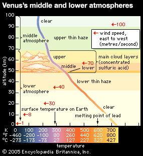
Reduction of ultimate tensile stress with the increase of temperature (kudos to @Uwe for pointing this out in the comments!).
What this means is all above calculations would have been applicable only if the temperature in the atmosphere of Venus was 20degC. But it's quite a bit hotter than that. Wikipedia states 460degC at the surface.
 Picture borrowed from here
Btw, it's apparently warmer and nastier at 50km altitude than I thought, hence I now start to question straight-forwardness of the reel motor and other mechanisms/electronics of the aerostat floating in ~80 deg C concentrated sulphuric acid clouds with 70m/s winds.
Also the large temperature differential may be a very big problem, as when we lift the probe up by winding the tether onto the reel if the hotter portions of the cable that were at the bottom don't cool down before they get onto the reel, they will contract when cooling down whilst being on the reel, which will result in significantly larger stress than calculated.
Quick search revealed that this article estimates around 8.5% reduction of strength at 200degC (as compared to strength at 20degC). It also reports room temperature strengh a bit lower than 3GPa, but let's hope we will get superior basalt quality for our tether and stick with 3GPa figure.
I couldn' find tensile stress data for basalt at 460degC, therefore let's make a conservative guess and assume it is going to drop 30%.
This gives us T=3GPa*0.7=2.1GPa.
With this result, our SF for tension drops from 3 to 2.1, SF for bending from 10 to 7, and overall SF from 2.3 to 1.6 (2.1GPa/1.3GPa). With such low SF, our nice and thin and lightweight tether is not likely to safely deploy the 100kg probe on the surface of Venus multiple times.
But it's not time to give up yet, one would say, we could make the tether a bit thicker!
Now that we've accounted for hot venusian climate (tensile stress reduction), let's see what our tether is going to look like in order to have a similar safety coefficient as originally planned (total SF will be 3.3 for the following example):
SF for tension = 5: operating tensile stress 2.1GPa/5=0.42GPa.
Taper ratio formula gives us the ratio of 16.9
(by the way, it looks like the OP has simplified the formula from the referenced answer and, when I use the formula from the body of the current question, the taper ratio is not very accurate, which is highlighted by the fact that I
always receive a higher stress when doing the cross check: (mass of probe + mass of tether)×gravity/(larger diameter of the tether))
The error has been attributed to incorrectly calculating tether volume (therefore mass) and not accounting for varying gravity across the height. The tether mass values in the examples below are now updated to the corrected ones.
We start from approx. double area: 2.11 sq.mm. and finish with 35.7 sq.mm. (1.64 and 6.74 mm diameter respectively)
The tether mass now grows from 270kg to quite disappointing 2,093 1,604 kg.
If we take SF for bending stress of 10, then our total SF will be 2.1GPa/(0.42GPa+0.21GPa)=3.3
and bending radius for a single wire 1.36 m.
We already came to conclusion that a vowen rope would be better suited for the application rather than wire, hence a smaller radius will correspond to the same bending stress (unfortunately, I don't know exactly how much smaller the radius will be).
As we see, the tether mass now already pose challenges whilst safety factor of 3.3 is still on the lower side of what is used for design of non-critical Earthly cranes.
Let's see how much we can push it to get a higher SF.
Below are results of two more calculations for SF 4.5 and 5.2:
- Total SF 4.5 (6.5 for tension and 15 for bending)
Taper ratio 39.5;
Areas: 2.75 to 108.4 sq.mm;
Diameters: 1.87 to 11.75 mm;
Bend radius: 3.5 m (I list the figure for single wire purely for comarison, remember it will be smaller for rope);
Tether mass:
5,778 3,884 kg.
- Total SF 5.2 (8 for tension and 15 for bending)
Taper ratio 92.2
Areas: 3.38 to 311.6 sq.mm;
Diameters: 2.07 to 19.92 mm;
Bend radius: 6.05 m (again, only for comparison, rope will accomodate smaller);
Tether mass: astonishing
15,640 9,199 kg.
So, to sum up, even though seemingly possible to utilize the design of SF 3.3 (taper ratio 16.9) for a very few cycles of the probe descending/elevation, the limit of what might be practically achievable from tether point of view seems to lie outside of realistically applied safety factors for reliable truly multiple cycles operation.
Achieving designs for safety factors in the range of human-rated lifting (if we ever wanted to utilise such an option on Venus) seems to be out of question even for this relatively short 50km space elevator.


