5
$\begingroup$

Looking at the 3rd edition of Space Mission Analysis and Design by Wertz and Larson, their equation (13-4) presents the link equation,

$\frac{E_b}{N_0} = \frac{PL_\ell G_t L_s L_a G_r}{k T_s R}$,

with $E_b/N_0$ being the receiver energy per bit over noise density, $P$ is transmitter power, $L_\ell$ is transmitter-to-antenna line loss, $G_t$ the transmit antenna gain, $L_s$ the free space path loss, $L_a$ transmission path loss (atmospheric and rain absorption, etc.), $G_r$ the receive antenna gain, $T_s$ the system noise temperature, $R$ the data bit rate, and $k$ the Boltzmann constant.

Their equation (13-13) then has the same equation in logarithmic (decibel) form:

$\frac{E_b}{N_0} = P + L_\ell + G_t + L_{pr} + L_s + L_a + G_r + 228.6 - 10\log{T_s} - 10\log{R}$

This equation is identical to (13-4) except for the addition of the $L_{pr}$ term. I cannot find the definition of $L_{pr}$. (Hopefully I'm not just missing it.) This term is in equation (13-14) as well but then seems to disappear.

What is $L_{pr}$? Is it a leftover term from a previous edition perhaps, or does changing the equation to logarithmic form somehow require adding that new term?
$\endgroup$
6
  • $\begingroup$ Are you sure you copied correctly Eq. (13-4)? (I don't have the book) $\endgroup$
    – Ng Ph
    Commented Jan 6, 2022 at 16:13
  • $\begingroup$ Yes, I am sure I copied Eq. (13-4) correctly. And even if I hadn't and had missed an $L_{pr}$ term, there is no definition for $L_{pr}$ in the discussion of that equation. $\endgroup$ Commented Jan 6, 2022 at 17:09
  • $\begingroup$ You know that Eq. 13-4 is applicable to BPSK modulation only, right? $\endgroup$
    – Ng Ph
    Commented Jan 6, 2022 at 18:19
  • $\begingroup$ @NgPh I'm new to radio communications. I didn't know that. The book gives no indication of that though (the modulation and coding section comes later in that chapter), and modulation does not come up anywhere in the derivation of the link equation. Given that, does that inform what $L_{PR}$ is? $\endgroup$ Commented Jan 6, 2022 at 21:51
  • $\begingroup$ No problem (we are here to share knowledge). The righthand side of 13-4 is an expression of signal-to-noise ratio (S/N). The numerator is the received signal power, the denominator is the noise power. (13-4) then equates S/N=Eb/No, and this is only possible for BPSK. Only for BPSK do we have S=signal power= Eb x bitrate and N=noise power = No x signal bandwidth = No x R. Hence it is weird for me that a book presents a general link equation with the special case of BPSK. $\endgroup$
    – Ng Ph
    Commented Jan 6, 2022 at 23:00

2 Answers 2

3
$\begingroup$

Lpr and Lpt would be pointing loss, receiver and pointing loss, transmitter, respectively.

$\endgroup$
1
$\begingroup$

As @TFC points out the $L_{p}$s are probably pointing losses due to pointing errors away from maximum gain. In this case the gains $G$ would have to be the maximum gains for ideally pointed antennas from which this pointing error loss should be deducted.

Alternatively you could drop the pointing losses and just define the gains as the actual gains of the antennas in the current direction of the link.

Just like there are several different styles of accounting and budgeting of money that can give the same result, there are different ways you can construct a link budget and define its terms, depending on how you'd like to look at it.

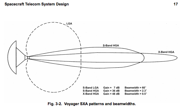
You can say that a Voyager spacecraft's high gain X-band antenna has a gain $G$ of 48 dB and that since it's currently pointed a half-degree away from Earth (just making up numbers here), its pointing loss is say -1 dB.

Or you could look up the gain of a Voyager's antenna in the direction that Earth sits relative to it and find that the current gain is 47 dB.

Six of one, a half-dozen of the other.


cf How well can Voyager 1 separate Earth signals from Solar noise these days? and for a plot of Earth's yearly wobble relative to the Sun as seen from the Voyagers (they are so far away now they don't bother to constantly change attitude for small deviations, and also probably can't afford to do that anyway) and a simple example of their radiation patterns and this answer to What is the pop-up circular disk with spiral pattern in this NASA animation of the Dragonfly helicopter for Titan? Antenna? Kind, band, target? and also How does Curiosity know how to point and move it's high gain antenna in real time? for screenshots of the radiation pattern for some other spacecraft.


Voyager's antennas' radiation patterns

above: From DESCANSO Design and Performance Summary Series Article 4: Voyager Telecommunications as discussed in this answer. below: from this answer (I can't currently find the exact attribution)

enter image description here

$\endgroup$

Your Answer

By clicking “Post Your Answer”, you agree to our terms of service and acknowledge you have read our privacy policy.

Not the answer you're looking for? Browse other questions tagged or ask your own question.