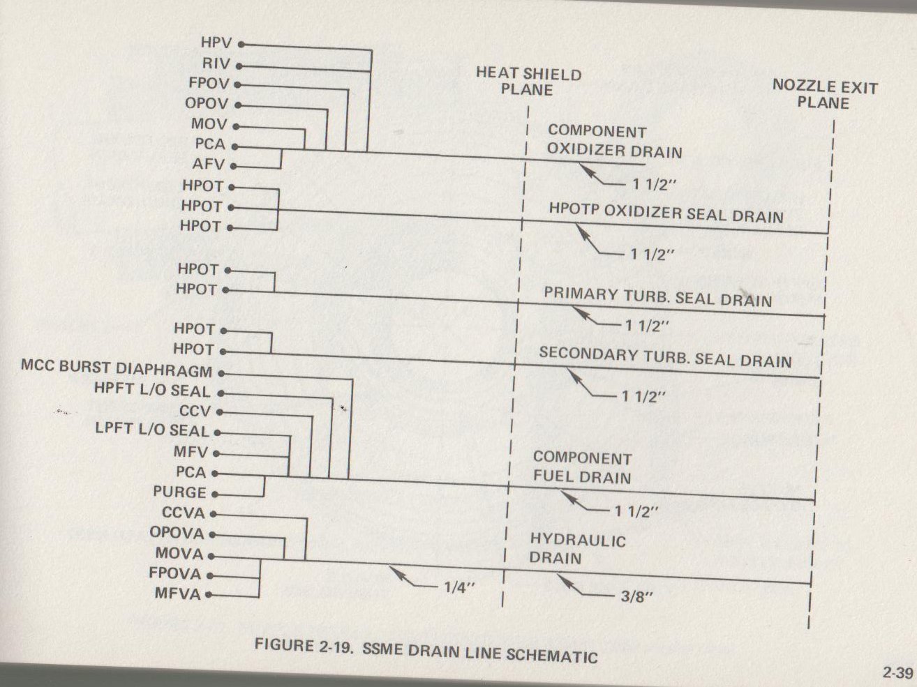
The lines that exited at the end of the nozzle were drain lines carrying leakage from seals, output of hydraulic actuator drain lines, etc. The following schematic shows the various systems attached to these drain lines. Source: Rockwell SSME Pocket Data Book, R/RD87-142.

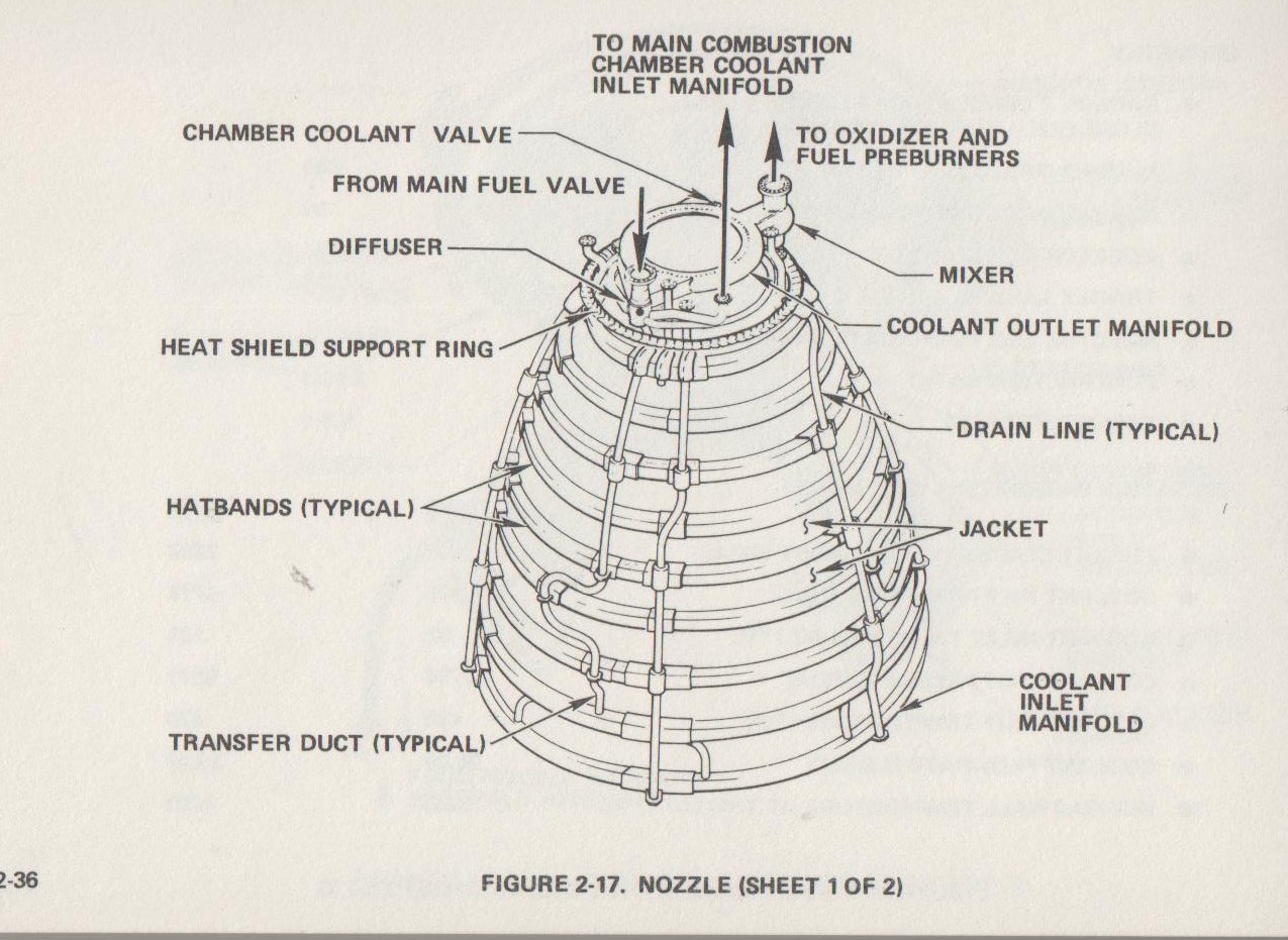
This graphic differentiates between the transfer ducts (which carried the hydrogen which cooled the nozzle) and the drain lines.

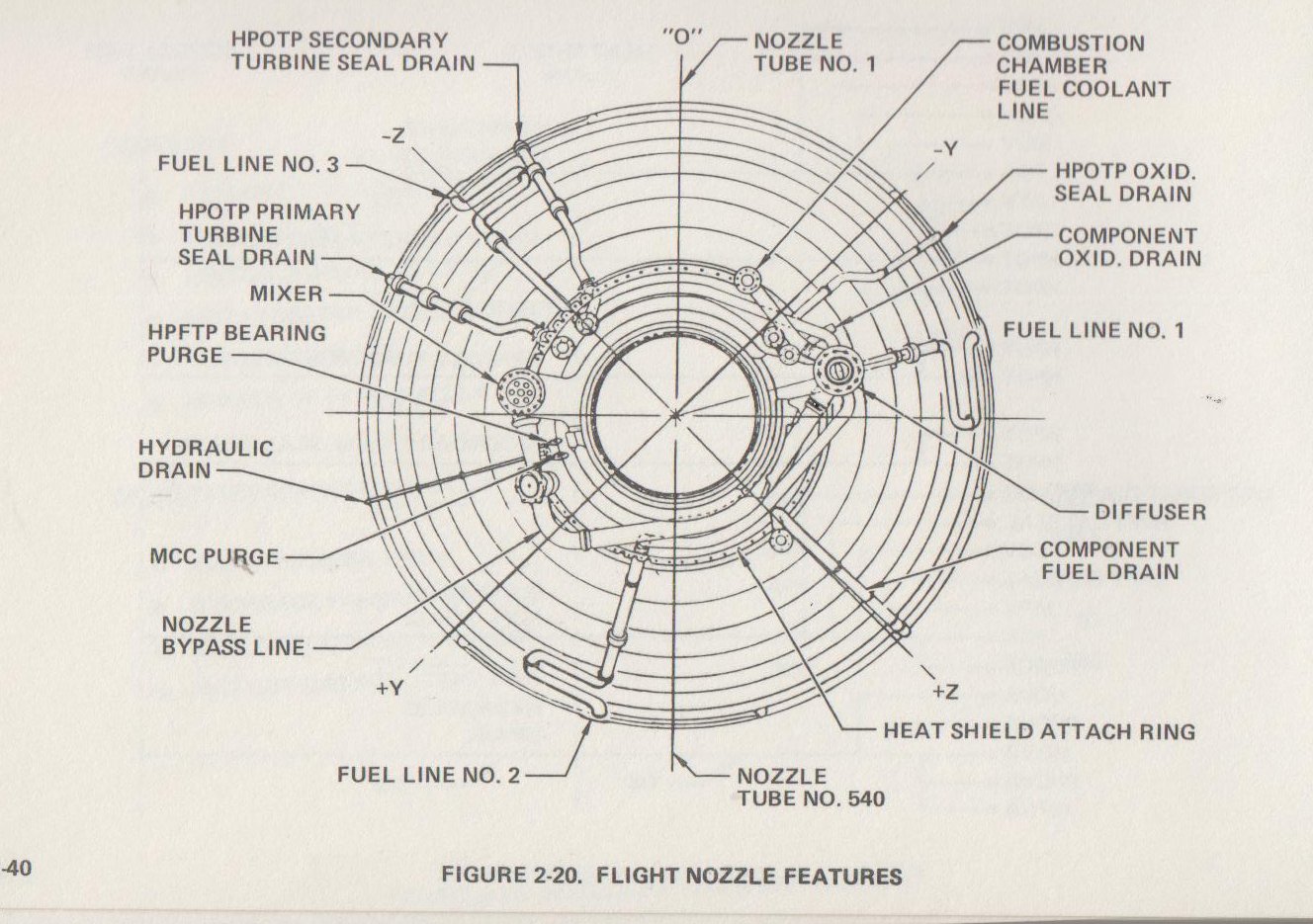
Finally, this graphic shows a "looking down the length of the nozzle" view with all the drain lines annotated.

Note: this answer represents a 1989 version of the SSME and may not be totally accurate for the versions flying at the end of the program; the important take-away is that what you see is only leakage, drainage, purge gas, etc, and not part of the propellant loops.


