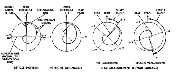
You're remembering the Apollo Lunar Module Alignment Optical Telescope which had that spiral reticle.

The alignment optical telescope is used for in-flight and lunar surface sightings.
For in-flight sightings, the telescope may be placed in any of the usable detent positions. However, when the LM is attached to the CSM, only the forward position is used. The astronaut selects a detent and the particular star he wishes to use. He then maneuvers the LM so that the selected star falls within the telescope field of view. The specific detent position and a code associated with the selected star are entered into the guidance computer by the astronaut using the DSKY. The LM is then maneuvered so that the star image crosses the reticle crosshairs. When the star image is coincident with the Y-line, the astronaut presses the mark Y pushbutton; when it is coincident with the X-line, he presses the mark X pushbutton. The astronaut may do this in either order and, if desired, he may erase the latest mark by pressing the reject pushbutton. When a mark pushbutton is pressed, a discrete is sent to the guidance computer. The guidance computer then records the time of mark and the inertial measurement unit gimbal angles at the instant of the mark.
Crossing of a reticle line by the star image defines a plane containing the star. Crossing of the other reticle line defines another plane containing the same star. The intersection of these planes forms a line that defines the direction of the star. To define the inertial orientation of the stable member, sightings on at least two stars are required. Each star sighting requires the same procedure. Multiple reticle crossings and their corresponding marks can be made on either or both stars to improve the accuracy of the sightings. Upon completion of the second star sightings, the guidance computer calculates the orientation of the stable member with respect to a predefined reference coordinate system.
On the lunar surface, the LM cannot be maneuvered to obtain a star-image that crosses the reticle crosshairs. The astronaut using the reticle control knob, adjusts the reticle to superimpose the orientation (Y) line on the target star. The reticle angle display on the reticle counter, is then inserted into the computer by the astronaut. This provides the computer with the star orientation angle (shaft angle). The astronaut then continues rotating the reticle until a point on the spirals is superimposed on the target star. This second angular readout (reticle angle) is then entered into the computer along with the detent position and the code of the observed star. The computer can now calculate the angular displacement of the star from the center of the field of view by computing the difference between the two counter readings. Due to the characteristics of the reticle spirals, the angle is proportional to the distance of the star from the center of the field-of-view. Using this angle and a proportionality equation, the computer can calculate the trunnion angle. At least two star sightings are required for determination of the inertial orientation of the stable member.
Note however, this procedure does not (and can't) measure their position, it measures their orientation.
Acronymology:
- CSM Command and Service Module
- DSKY Display and Keyboard
- LM Lunar Module
