5
$\begingroup$

I'm working on this question. This is the farthest (known) communications link humans have ever engineered - an one node is running in deep space on 40 year old technology. Pretty amazing!

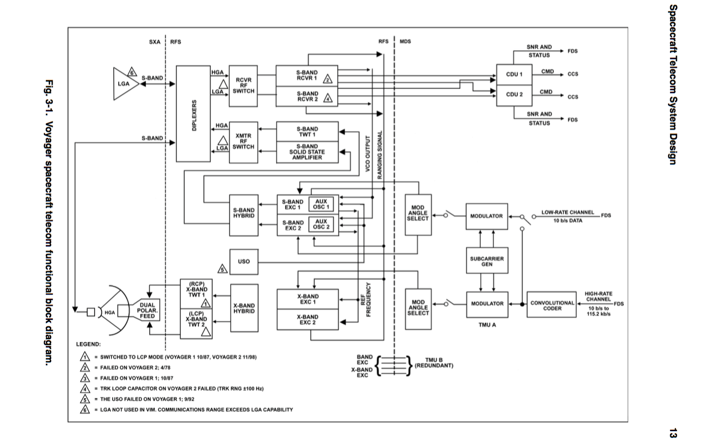
In the DESCANSO Design and Performance Summary Series, the NASA document Article 4 - Voyager Telecommunications has a nice block diagram as Figure 3.1 on page 13. A screen shot is shown below.

Question: Where can I see the frequency response of the S-band feed horn at the primary focus, and the S-band receiver front end and IF engineering specs (pass band(s), out-of-band rejection, etc.) and schematic?

I'm primarily interested in the parts that have to cope with, and remove most of the powerful, broad-band radio noise from the sun before any of the final demodulation/correlation.

If you have some representative values that would be great - if you can go ahead and answer the other question linked above - related to rejection of noise from the Sun - that is even greater! But please give me a source, link, or citation or two so I can go reading further. I'm really amazed by this spacecraft and the engineering that went into it - thanks!

Voyager Radio System - NASA

above: from Voyager Telecommunications - click for full size.
$\endgroup$
6
  • $\begingroup$ Yay! (I think) I've eared a Tumbleweed award for this question. That means it's really a good question - right? I'm trying to get more background information so I can keep working on this Voyager communications question How well can Voyager 1 separate Earth signals from Solar noise these days? Even an substantially imperfect answer will be most appreciated! $\endgroup$
    – uhoh
    Commented Jul 30, 2016 at 4:32
  • $\begingroup$ How about you edit this to ask for the specifics with references, rather than ask for the references themselves? Also a title that better summarizes what you are actually asking for might help... $\endgroup$
    – user
    Commented Jul 30, 2016 at 11:16
  • $\begingroup$ @MichaelKjörling it's a good suggestion. I didn't want to write too narrow thereby excluding something that I could have found useful, there may not be much out there and I didn't want to be too picky. But OK, I'll rewrite per your suggestion. It will be about the S-band High Gain feed horn and the S-band receiver front end and IF sections - frequency responses, filters, circuit diagram and engineering discussion/ characterization. I'll assume the diplexers and switches are just impedance matched passive elements. $\endgroup$
    – uhoh
    Commented Jul 30, 2016 at 11:29
  • $\begingroup$ @MichaelKjörling But I want to avoid the situation where someone is holding the information in their hand and dolling it out a little bit at a time. It's much more useful if someone points me to the archive where then answer likely to be than if they just say "the 3dB width of the feed horn is 20 MHz and you don't need to know anything else to do what you are doing so I'm not going to tell you." because I know what a pain it can be when one of the early stages is saturating with noise outside a later stages passband such that you don't see it directly but you just can't get good copy. $\endgroup$
    – uhoh
    Commented Jul 30, 2016 at 11:38
  • 1
    $\begingroup$ That's part of the reason why I suggested asking for answers with references. That way, there's a specific question, but also a source for you to go check for more. $\endgroup$
    – user
    Commented Jul 30, 2016 at 11:50

0

Your Answer

By clicking “Post Your Answer”, you agree to our terms of service and acknowledge you have read our privacy policy.

Browse other questions tagged or ask your own question.