10
$\begingroup$

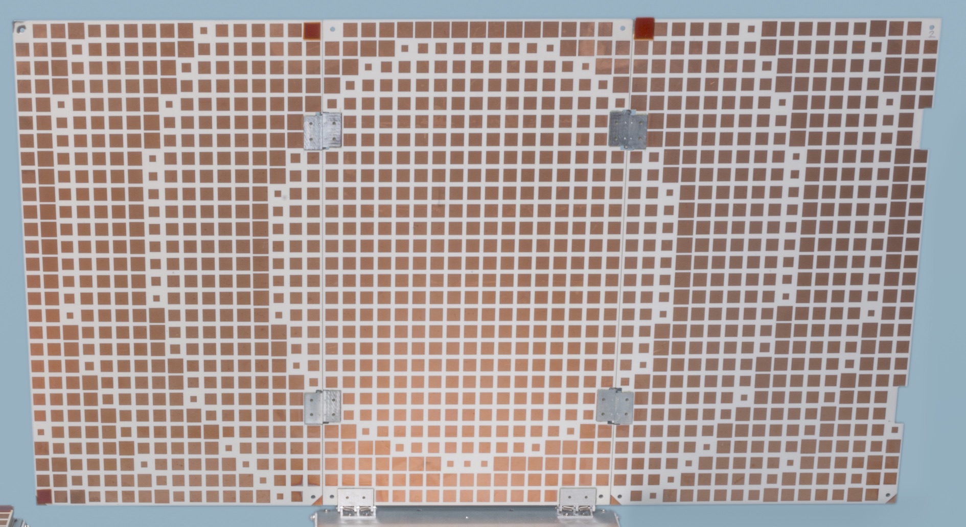
I was looking at a few posts that uhoh had made about the MarCo cubesat. One of the pictures was the one that I've posted below:

MarCO cubesat NASA PIA22319

Source

The most I can gather from casual NASA articles is along the lines of:

The high-gain, X-band antenna is a flat panel engineered to direct radio waves the way a parabolic dish antenna does.

While the design visually looks as if it's a parabolic-style pattern, I would like a few more specifics on the following:

  • What materials are in this "pseduo-parabolic" antenna (mostly asking about the gold squares).
  • How do the sizes of the squares affect the power of the antenna, I'm sure they are not arbitrary.
  • How does the overall design/pattern affect the power of the dish and why?

If you have a link to any papers about the antenna that would be awesome as well, thanks.


Alex provided a wikipedia link which led me to find:

On board the two CubeSats is an ultra-high frequency (UHF) antenna with circular polarization. EDL information from InSight was transmitted through the UHF band at 8 kbit/s to the CubeSats, and was simultaneously retransmitted at an X band frequency at 8 kbit/s to Earth. MarCO used a deployable solar panel for power, but because of the limitations in solar panel efficiency, the power for the X-band frequency can only be about 5 watts.

So it seems the shape of the design on the antenna was designed with circular polarization in mind; what that actually means in terms of antennas though, I do not know. The wikipedia article links to this IEEE article which I do not have access to read.
$\endgroup$
4
  • 1
    $\begingroup$ From what i've found i think it's a reflective array antenna. See the wiki on the topic here. I don't know much about RF unfortunately so can't help you much more than this. $\endgroup$ Commented Mar 13, 2019 at 16:20
  • $\begingroup$ @AlexanderVandenberghe the closest thing to an explanation I've found through "wikidiving" is that it's utilizing Circular Polarization, as to how it does, I've not the foggiest. $\endgroup$ Commented Mar 13, 2019 at 16:30
  • 2
    $\begingroup$ You should look into phased-array antennas. By utilizing many small antennas, the wavefront can be shaped. By making the antennas different sizes, the timing requirements for a phased array antenna are relegated to the physical shape of the individual patch antennas and thus is much simpler to drive but less configurable than a phased array system. $\endgroup$
    – Dragongeek
    Commented Mar 13, 2019 at 17:05
  • 2
    $\begingroup$ @MagicOctopusUrn The polarization of a signal is essentially it's angle. A circularly polarized antenna will be able to transmit and receive no mater what angle it's at (provided it's pointing towards the target) $\endgroup$
    – Dragongeek
    Commented Mar 13, 2019 at 17:09

2 Answers 2

9
$\begingroup$

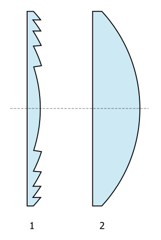
It's the electrical equivalent of a Fresnel mirror; the reflective cousin of a Fresnel lens.

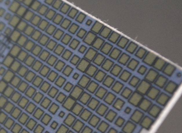
Each of the little square patterns is actually a little passive circuit that reflects the incident microwaves with a different phase shift.

It is called a Reflectarray antenna. You can read more about it in this Researchgate paper A Deployable High-Gain Antenna Bound for Mars: Developing a new folded-panel reflectarray for the first CubeSat mission to Mars.

enter image description here

Paywalled: The Mars Cube One deployable high gain antenna

Open Access: Reflectarray antennas: A review

The surface emulates a concave mirror, so the center needs to be the "deepest" and so the large squares delay the reflection the most. Moving out from the center the patterns delay less and less. But once you get to 360 degrees it's the same as zero, so it can go back to the longest delay.

The electrical shape emulates an off-axis parabola, optically a lot like modern satellite dish antennas.

In the mean time you can read the article in Hackaday: Interview: Nacer Chahat Designs Antennas for Mars Cubesats and you can also watch the video below.

You can also read more about MarCo hardware systems in this answer.

enter image description here Source

enter image description here

above: Source Click for full size

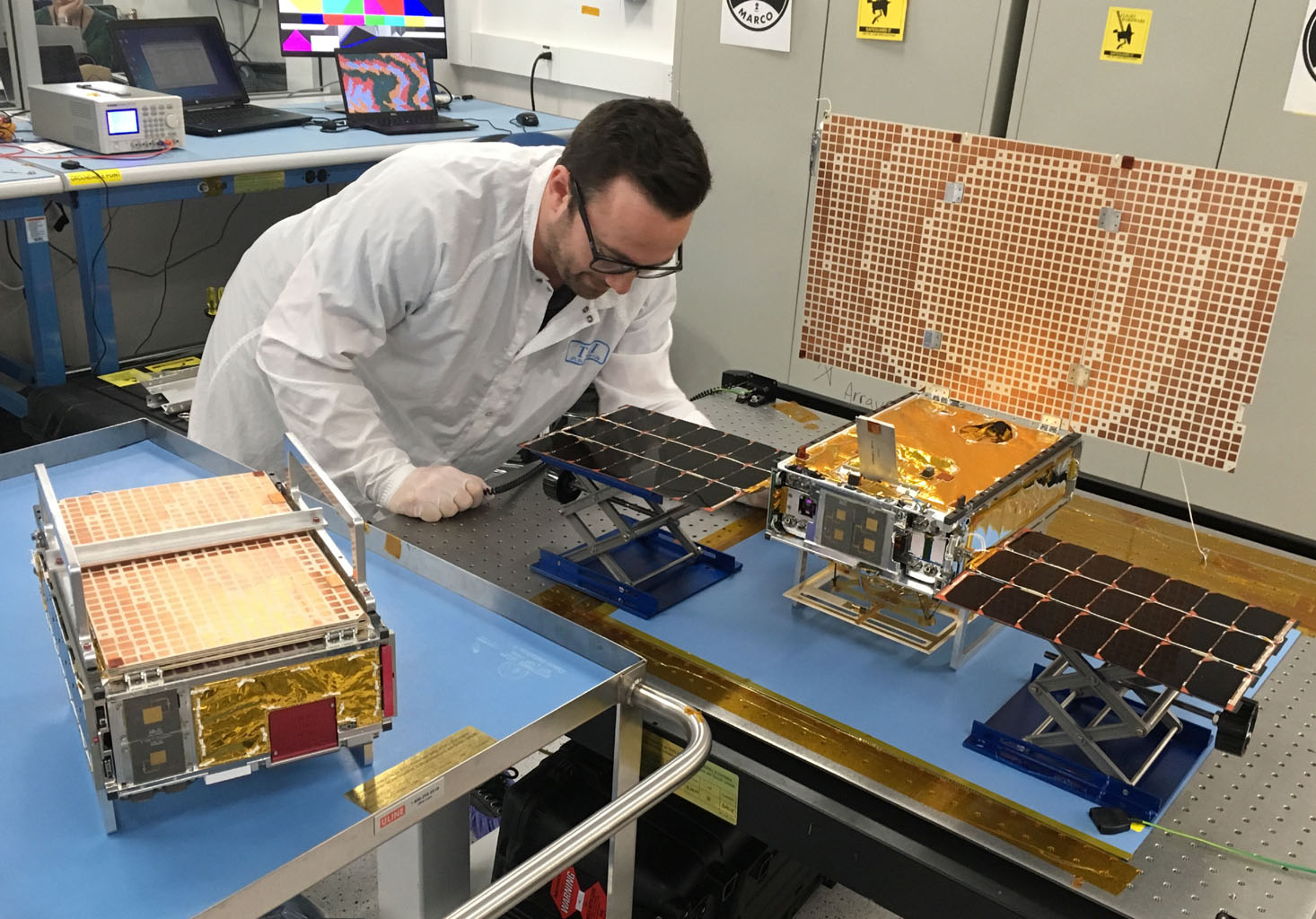
The X-band antenna that transmits back to earth folds into three panels. When deployed, the reflector array is wider than it is tall so the signal source also has an array to utilize the full reflector. Interestingly, the pattern you can see on the reflector array helps the flat panels act more like a parabolic reflector. MarCO is also capable of receiving X-band from Earth using the array seen on the front face of the folded model above. These CubeSats are unable to transmit on the UHF band, they only receive the UHF communications from ground vehicles.

enter image description here

above: Source "MarCO Cube Sat. X-band antenna"


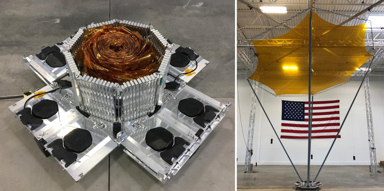
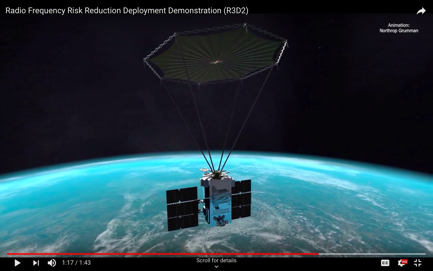
Here's another reflectarray antenna. From DARPA Prototype Reflectarray Antenna Offers High Performance in Small Package and Electron | DARPA R3D2 | Rocket Lab, though they don't show the details of the pattern required here:

R3D2 reflectarray

Screenshot from Radio Frequency Risk Reduction Deployment Demonstration (R3D2):

enter image description here


$\endgroup$
3
  • $\begingroup$ Oh my that closeup is beautiful, do ping me if you get the paper linked. I'll check out that hack-a-day source right now :)! That pattern is definitely more complex than my first at-a-glance could tell. $\endgroup$ Commented Mar 13, 2019 at 18:19
  • $\begingroup$ No rush, this is awesome. The Fresnel lens / mirror comment gives me a lot to go on! $\endgroup$ Commented Mar 13, 2019 at 18:20
  • 1
    $\begingroup$ @MagicOctopusUrn I've added some papers. $\endgroup$
    – uhoh
    Commented Mar 13, 2019 at 18:37
6
$\begingroup$

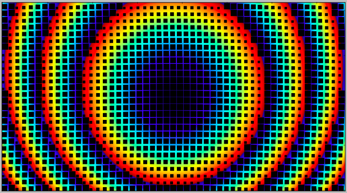
Here's how to calculate the path lengths and the required phase shift to make it work. I've added a cartoon representation of squares that vary with required phase shift just to show how a real scenario might be calculated in Python.

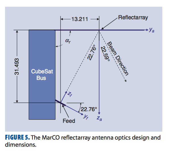
I used the dimensions in this image in this answer and a round figure of 8.4 GHz but the sizes of the zones don't match perfectly. I'll leave it as-is rather than fudge the numbers, it's an interesting residual puzzle!

MarCO antenna faux calculation

MarCO antenna

import numpy as np
import matplotlib.pyplot as plt
import matplotlib.patches as patches

halfpi, pi, twopi = [f*np.pi for f in (0.5, 1, 2)]
degs, rads = 180/pi, pi/180

clight     = 2.9979E+08      # m/s
d, h, w,   = [0.01 * thing for thing in (31.5, 33.5, 59.7)] # meters
nx, ny     = 51, 28
nn         = 15
nnx, nny   = [nn*n for n in (nx, ny)]
dx, dy     = w/nnx, h/nny

hh, hw     = 0.5 * h, 0.5 * w
hfeed      = hh - 0.01 * 13.2
freq       = 8.4E+09         # Hz, roughly
lam        = clight/freq     # meters

theta      = rads * 22.59

X_feed     = np.array([0, hfeed, -d])

print "w, h: ", w, h
print "nx, ny: ", nx, ny
print "dx, dy: ", dx, dy

y = dy * (np.arange(nny) + 0.5)
x = dx * (np.arange(nnx) - 0.5*(nnx-1))

Y, X = np.meshgrid(y, x, indexing='ij')
Z    = np.zeros_like(X)
XYZ  = np.stack((X, Y, Z), axis=2)

r_zero   = np.sqrt(((XYZ - X_feed)**2).sum(axis=2))

OPL      = r_zero - Y * np.sin(theta)
phase    = twopi * np.mod((OPL-OPL.min())/lam, 1)

iX  = nn/2 + nn*np.arange(nx)
iY  = nn/2 + nn*np.arange(ny)
pairs = sum([[(iy, ix) for ix in iX] for iy in iY], [])
vals  = phase[zip(*pairs)]

rects = []
for pair, val in zip(pairs, vals):
    w = (nn-6) * (1-val/twopi) + 4
    y0, x0 = pair[0] - nn/2, pair[1] - nn/2
    rect = patches.Rectangle((x0,y0),w,w,linewidth=1,edgecolor=None,facecolor='k')
    rects.append(rect)

if True:
    fig = plt.figure()
    ax  = fig.add_subplot(1, 1, 1)
    wow = ax.imshow(phase, origin='lower')
    plt.colorbar(wow)
    # ax.set_title('phase')
    for rect in rects:
        ax.add_patch(rect)
    ax.set_xticklabels([])
    ax.set_yticklabels([])
    plt.show()
$\endgroup$

Your Answer

By clicking “Post Your Answer”, you agree to our terms of service and acknowledge you have read our privacy policy.

Not the answer you're looking for? Browse other questions tagged or ask your own question.