@NgPh's answer to How will the LICIACube cubesat transmit DART impact images back to Earth? What kind of antenna and radio will it use? quotes LICIACube on DART mission: an asteroid impact captured by Italian small satellite technology (SSC20-WKIII-06 from the 34th Annual Small Satellite Conference):
A paper authored by Simonetti: LICIACube on Dart Mission ... provides corroboratively the following information:
The [communication] subsystem includes an X-Band transponder that manages downlink and uplink communications and is connected to four X-Band patch antennas.
Hence, the X-band is confirmed. Further,
The set of antennas consists of:
- The main pair composed by a transmitting antenna, with 22 dBi gain, and a receiving antenna, with 6 dBi gain, both placed in the solar side structural panel;
- The secondary pair composed by a transmitting antenna, with 12 dBi gain, and a receiving antenna, with 6 dBi gain, both placed at the opposite side of the main pair.
In this answer I find that an X-band downlink (space to Earth) frequency may be about 8.4 GHz. For a circular aperture which approximates a flat patch antenna array as well as a sphere approximates a cow, a wavelength of 3.56 cm would need a "dish" diameter of
$$G \approx \left( \frac{\pi D}{\lambda} \right)^2$$
$$D \approx \frac{G^{1/2}}{\pi} \lambda \approx 4 \lambda \approx 14 \text{cm}.$$
Dart is a 6U cubesat so one 10 x 30 cm side could easily support a patch antenna of a similar area, so the numbers work.
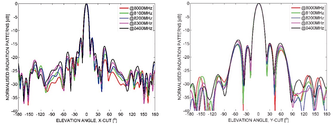
But the radiation pattern of the patch array could be complicated and lumpy and offer maximum gain in an awkwardly shaped pattern constraining the spacecraft attitude during transmit modes.
Recall that a patch array will likely be some planar arrangement of individual flat radiators in such a way that their amplitudes add in-phase in a given direction, mostly likely normal to the surface. Such a planar, passive like the single user Starling ground terminals. where the elements have different and variable phases so as to steer the beam.
- How should we point our SpaceX Starlink ground transceiver antennas?
- How does this SpaceX Starlink ground station antenna's gear mechanism move it in both altitude and azimuth?
- Ars Technica's Teardown of “Dishy McFlatface,” the SpaceX Starlink user terminal links to the YouTube video Starlink Teardown: DISHY DESTROYED!
That's opposed to a phased array where the elements are phased in groups or individually in order to steer the beam electronically.
So I'd like to ask:
Question: How does a 22 dBi X-band "patch" antenna get so much gain and how well behaved is its high-gain radiation pattern?

