Like the SSRMS itself, it's rather complicated.
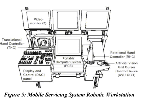
The "control panel" is called the Robotics Workstation (RWS). There are two of them onboard the ISS. One is in the US Lab, the other in the Cupola. An RWS consists of four main parts.
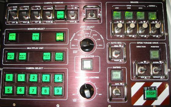
- The Display and Control Panel, which has hardware switches for
- Camera routing and control
- Joint selection for single joint control mode
- Brakes
- Safing
- Auto Sequence control
- Special Purpose Dextrous Manipulator (aka Dextre) controls
Some limited feedback is provided here by illumination of the buttons.
The joysticks, one for rotation and one for translation. The translational control on the left can be pushed in, pulled out, moved left or right, and/or up and down, for +/- directions in all three translations axes. The rotational control on the right can be pitched up or down, rolled left or right, and yawed (twisted) in both directions, for +/- motion in all rotational axes. This is a common setup with Shuttle piloting and Shuttle robotic arm controls working in the same fashion. A trigger on the rotational control allows the user to grapple or release.
Three dedicated CCTV monitors to show camera views. The RWS generates and displays useful overlays on the monitors showing camera data, joint angles, alignment to grapple target, etc. Critical feedback to the operator(s) can be provided through these overlays so that the operator(s) does not have to look away from the monitors.
A dedicated Portable Computer System (PCS) laptop used to call up the displays for controlling the SSRMS. Additional PCSs can be used if desired. Most of the detailed feedback to the operator(s) is shown on the PCS displays, and detailed control information is entered here.
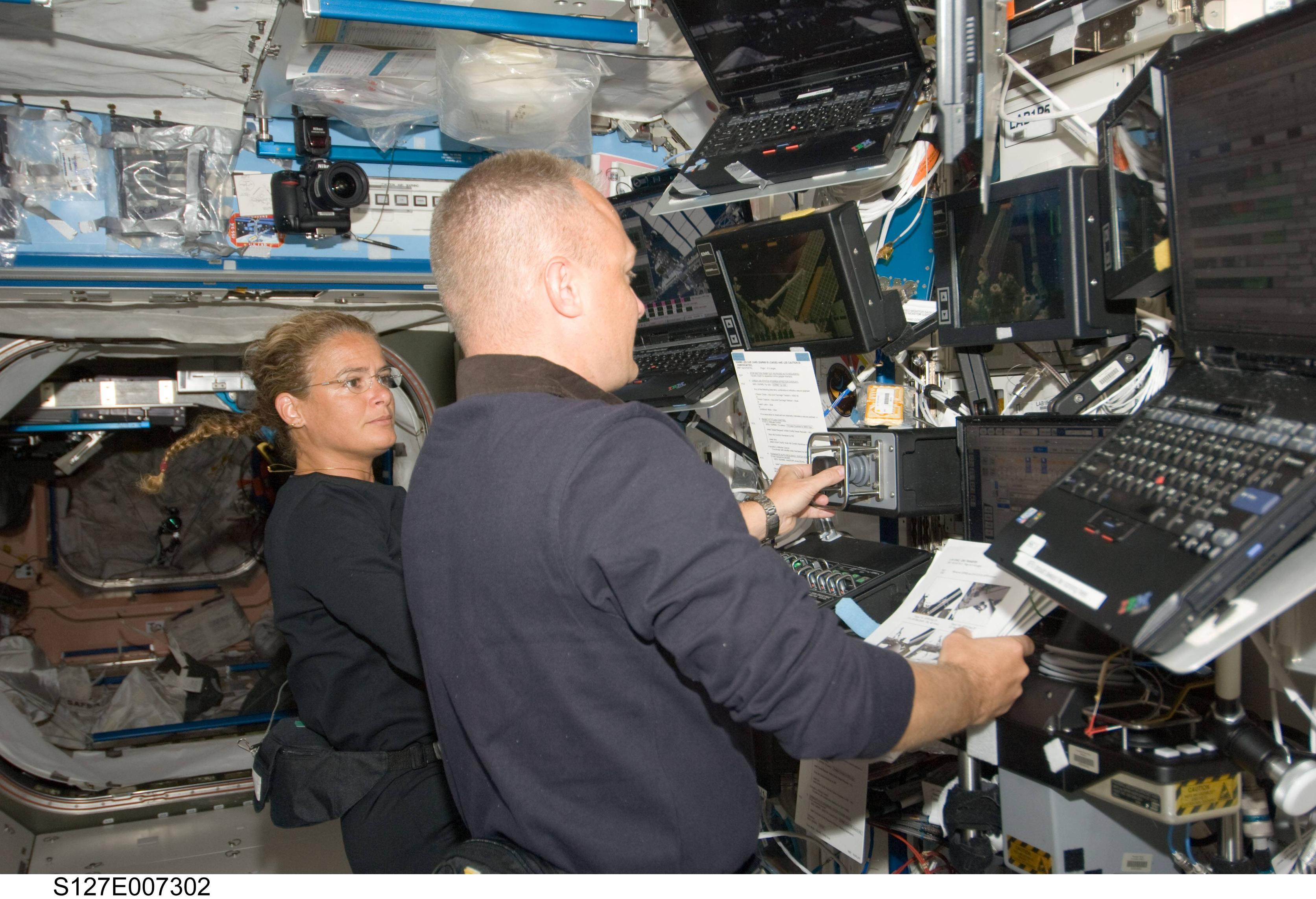
This is the RWS in the Lab.
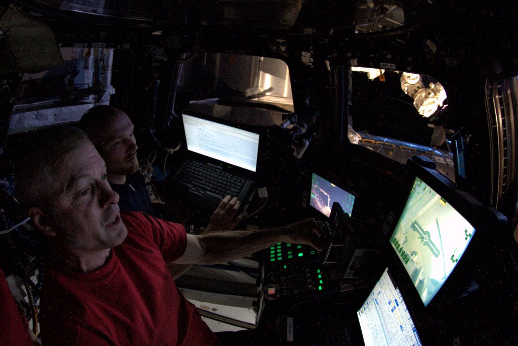
 And this is the RWS in the Cupola.
As far as modes of operation, as alluded to above, the operator can control one joint at a time, this is called Single Joint mode. There are many modes of operation besides single joint
- FOR manual modes, in which the operator controls the motion of a given Frame
of Reference, often the tip of the arm
- Pitch Plane mode, which rotates the pitch plane while maintaining
the chosen FOR
- FOR Operator Commanded Auto Sequence (OCAS) mode, which moves the
chosen FOR from a chosen initial to final position and attitude
- FOR Autosequence, which moves the chosen FOR through a
preprogrammed sequence of points
- Joint OCAS, which moves the joints to an operator specified set of
joint angles
- Joint Autosequence,which moves the joints through a preprogrammed
sequence of joint angles
Frames of Reference are key to SSRMS operations.
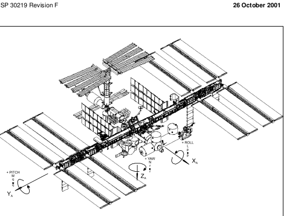
- The "external" frame is called the ISS Analysis Coordinate System
(ISSACS). It's a right-handed frame with the origin at the center of
the S0 Truss. The X axis points to ISS forward, the Z axis points to
ISS nadir, and the Y axis points ISS starboard. When you need to describe the position and attitude of something relative to the entire ISS, this frame is useful.
- A commonly used "internal" frame is the LEE (Latching End Effector,
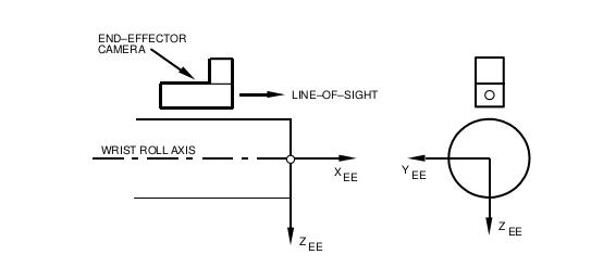
i.e. the tip of the arm) frame. This frame's origin is at the center of the LEE cavity. Its X axis points out of the LEE, the Z axis is away from the LEE mounted camera, and the Y axis completes the right-handed system. This frame is useful for describing the position and attitude of objects relative to the tip of the SSRMS.
- Each PDGF has its own frame, useful for describing the position and attitude of objects relative to the grapple fixture.
- Payloads grappled by the SSRMS have their own frames, sometimes
defined in terms of berthing hardware or cameras.
Final note: Everything can be controlled from Mission Control, and often is. Usually only highly critical operations like grappling or EVA support are done by the onboard crew.
Sources:
ISS Robotic Systems and Operations
ISS Coordinate Systems Manual
Personal notes


