10
$\begingroup$

My Question: What is the nature of the "experimental passive radar reflector developed by the U.S. Navy’s Space and Naval Warfare Systems Command"? How does it work, and why does it work for only a narrow range of radar frequencies?

Related question: Are SpaceBEEs actually hard to track?


The IEEE News article FCC Accuses Stealthy Startup of Launching Rogue Satellites focuses mostly on the intrigue addressed in the question What checks are supposed to be carried out to prevent illegal satellite launches? but I'd like to focus on the technical issues raised.

The SpaceBee-1, 2, 3, and 4 spacecraft look like this:

enter image description here

above: From IEEE "Images: Top: ISRO; Bottom: Swarm Technologies"

These are 1/4 U cubesats, only about 2.8 cm tall.

According to the IEEE article:

he FCC is responsible for regulating commercial satellites, including minimizing the chance of accidents in space. It feared that the four SpaceBees now orbiting the Earth would pose an unacceptable collision risk for other spacecraft.

The article goes on to say:

“As an object gets below 1U in size, it gets difficult to track, which means it’s harder to predict if there’s going to be a conjunction with another satellite,” says Marcus Holzinger, an aerospace professor at the Georgia Institute of Technology and expert on orbital safety. “Anything that size impacting at orbital velocities can be catastrophic.”

Swarm Technologies had realized that the small size of its BEEs might be a problem. It installed a GPS device in each satellite that would broadcast its position when requested. It also covered each of the satellite’s four smallest faces with an experimental passive radar reflector developed by the U.S. Navy’s Space and Naval Warfare Systems Command. According to Swarm’s FCC application, this would increase the BEE’s radar profile by a factor of 10.

But the FCC was not buying it. After correspondence back and forth through the summer, the FCC sent Swarm a letter in early December. In it, Anthony Serafini, chief of the FCC’s Experimental Licensing Branch, noted that the radar reflector only operated in a certain frequency band, corresponding to “a small portion” of America’s ground-based Space Surveillance Network. He also worried that GPS data would only be available while the satellite was functional.

Holzinger shares the agency’s concerns. “If there’s a software glitch, the satellite is going to become a passive piece of debris,” he says. “And while the reflector is certainly more robust, it may not amplify radar from a sensor using [a different] frequency band.” (Emphasis added).

While still waiting for an answer, the question What would be a “big picture” understanding of how the orbits of Earth satellites are monitored? includes a brief discussion of both radar and optical tracking, and the answer to Are 1U cubesats sufficiently detectable to get at least minimally usefully predictive public TLEs, updated regularly? addresses the already present challenges with fully-1U cubesats.

I would have thought that the roughly 1 meter long antenna would have contributed significantly to the spacecrafts' radar cross section already, but this does not seem to have been enough to assuage regulatory concern.

Ideally looking for a(n at least somewhat) supported answer if possible, not just a "well it could be a..." Thanks!

$\endgroup$
8
  • $\begingroup$ IIUIC, a ~1m long antenna only reflects brightly at ~300MHz and harmonics thereof. Existing space surveillance radars might not operate in a suitable frequency range. $\endgroup$ Commented Dec 22, 2018 at 1:04
  • 1
    $\begingroup$ @AlexHajnal small antennas can still be resonant if they have passive components. Examples include "chip antennas" used inside some small WiFi & BlueTooth devices and these familliar devices The passive radar reflectors are not the long flexible rods, they are probably the geometrical flat patterns on faces. $\endgroup$
    – uhoh
    Commented Dec 22, 2018 at 1:36
  • $\begingroup$ In my above comment I was referring to the paired whip antennæ used by the primary payload. $\endgroup$ Commented Dec 22, 2018 at 2:05
  • 1
    $\begingroup$ @AlexHajnal in PC boards flat pads of copper on two different layers can have significant capacitance, and long spiral lines can have significant inductance. If you've ever seen a flat RFID tag you might have seen a spiral pattern in it; that's an inductor. $\endgroup$
    – uhoh
    Commented Dec 22, 2018 at 2:17
  • 1
    $\begingroup$ Right. In some cases an entire circuit can be etched into a PCB with no need to solder on additional components. This is particularly true in the RF domain IIRC. $\endgroup$ Commented Dec 22, 2018 at 2:21

1 Answer 1

10
+200
$\begingroup$

The original 4 satellites were 0.25U cubesats (as shown in the picture in the question) while the newer ones are 1U (cubical). The larger size of the newer sats provides space for Van Atta reflectors on four of the cube's faces1. Here's my understanding2 of how the reflectors work:

In their most basic form, Van Atta reflectors are fully passive phased-array retroreflectors that are flat and thin. They consist of a symmetric array of patch antennæ with opposite pairs connected by waveguides. When a signal is received by an antenna it travels along the waveguide and is re-transmitted by the paired antenna. The length of each waveguide is such that the retransmited signal will, in the frequency domain3 and across the entire array, be identical to received signal except that the retransmitted signal is 180° out of phase with the received signal. Thanks to interference of the retransmitted signals, the wavefront of the aggregate signal will be pointed back to the original (active) transmitter.

Each signal4 sent through the reflector must be long enough that the retransmitted (delayed) waves can interfere. In addition, the delays of the waveguides are tuned to a specific frequency with the length of each waveguide directly related to the desired working frequency5. If these conditions aren't met then the reflector won't function correctly. Note however that there is no requirement that outbound interfering waves be from the same inbound pulse6.

Example layout of a Van Atta reflector (numbers indicate paired antennæ):

.-------------------------.
| .---. .---. .---. .---. |
| | 1 | | 2 | | 3 | | 4 | |
| '---' '---' '---' '---' |
| .---. .---. .---. .---. |
| | 5 | | 6 | | 7 | | 8 | |
| '---' '---' '---' '---' |
| .---. .---. .---. .---. |
| | 8 | | 7 | | 6 | | 5 | |
| '---' '---' '---' '---' |
| .---. .---. .---. .---. |
| | 4 | | 3 | | 2 | | 1 | |
| '---' '---' '---' '---' |
'-------------------------'

Two portions of the design are frequency-sensitive: the size of the antennæ and the lengths of the waveguides. For optimal performance the width and height of each antenna should be an integer multiple of the design wavelength (or vice-versa); if this is not done then the antenna will still work but at a much lower efficiency. In addition, I believe the spacing between the active elements and the groundplane should also have a similar relationship to the target wavelength. As mentioned above, the waveguide delays are directly related to the working frequency; if the delays are off then the phasing will be wrong and beamforming of the reflected signal won't be correct.

Typical patch antenna:

       +-----------+
       |           |
       |   +---+   |
feed ------|   |   |--- ground
       |   +---+   |
       |           |
       +-----------+

The ground plane is a continuous conductive surface behind and electrically-isolated from the active (fed) element.

Such patch antennæ are often constructed using standard PC board manufacturing techniques with the active elements etched on the front of the board and the solid groundplane on the back. The PC board itself acts as the dielectric spacer. The waveguides are typically wires or simply etched traces on the PC board (stripline/microstrip). Being completely flat surfaces, Van Atta arrays on PC boards can be made to occupy much less volume and weight than e.g. a corner reflector of similar performance. In addition, Van Atta reflectors have much lower losses at shallow angles than other reflector designs.

With the addition of some active circuitry, a message can be amplitude modulated onto the return signal. This is can be done, e.g., by placing PIN diodes inline with each waveguide. By switching the diodes between low-impedance and high-impedance to RF, the strength of the returned signal can be varied; this allows a relatively low-bandwidth (<1MHz) message to be returned. Note that the return-signal bandwidth is further constrained by the length of the delay lines which must be long enough to allow the transmitted signal to self-interfere. The newer SpaceBEEs are known to return their GPS positions on request; the technique described above might be the method used.


I'll take another look at this answer in a bit since I'm sure there's things that could be stated a bit more clearly.


1 Per https://space.skyrocket.de/doc_sdat/spacebee-5.htm

2 I do not have formal training in EE or RFE so corrections are welcome.

3 But not typically the time domain. The only time the transmitted signal will be the same in both domains is when it is received exactly perpendicular to the antenna plane. (I could be wrong about this)

4 A signal being defined (by me) as multiple, contiguous cycles of a wave from the point of view of the original transmitter.

5 $L_{waveguide} = (N + 0.5)\ \lambda : N \in \{ 0, \mathbb{Z}^+ \}, \ \lambda$ = design wavelength

Note that this presumes that the wave travels through the waveguide at $C$. In reality the wave will likely travel through the waveguide at a slower speed and the design will need to take this into account.

6 A pulse being defined (by me) as one complete, contiguous cycle of the transmitted wave from the point of view of the original transmitter.


The original patent and some papers on the topic (thanks to uhoh for pointing these out):


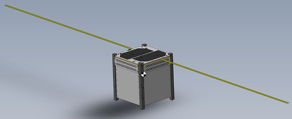
New design (SpaceBEE 5-8; 9-11 are similar):

Rendering of a 1U SpaceBEE

Source: Swarm Technologies via Erik Kulu, Nanosatellite & CubeSat Database, www.nanosats.eu
The Van Atta reflectors are likely located behind the large square blank panels in the lower portion of the satellite.


update: From January 2019: Swarm Wants to Send Hundreds of Tiny CubeSats Into Orbit; A notorious startup asks FCC for permission to launch a 150-strong constellation of small IoT satellites

enter image description here

Second, the satellites will carry radar retroreflectors, developed at the federal Space and Naval Warfare Systems Center, in San Diego, to boost their visibility to ground-based stations. Similar reflectors fitted to the illegally launched SpaceBEEs have shown that they are at least as visible as some larger 1/2U and 1U satellites in similar orbits.

A study by the space tracking firm LeoLabs (paid for by Swarm) found that the SpaceBEEs could be detected more than once a day on average, which was better than some larger satellites. Swarm has also contracted with LeoLabs to track its new constellation and provide a second source of orbital data to supplement the U.S. government’s Space Surveillance Network. A GPS chip will also regularly beam the satellite’s position down to Swarm HQ.

$\endgroup$
6
  • 1
    $\begingroup$ This is a great answer, thank you for going into such detail explaining the principle involved! $\endgroup$
    – uhoh
    Commented Dec 21, 2018 at 12:51
  • 1
    $\begingroup$ De nada. I learned something today :^) $\endgroup$ Commented Dec 21, 2018 at 12:52
  • $\begingroup$ So do you think that these are the elements of the passive retroreflector? $\endgroup$
    – uhoh
    Commented Dec 22, 2018 at 1:41
  • 1
    $\begingroup$ Possible but doubtful. 1) Those elements appear on the earlier 0.25 U SATs that don't have an enhanced RCS. 2) Van Atta reflectors work best with (strongly) 2D arrays which the newer 1 U SATs appear to have ample space for. The arrays are probably behind the large blank panels on the sides of the sats. $\endgroup$ Commented Dec 22, 2018 at 2:01
  • $\begingroup$ I'd had an earlier +100 bounty on this question, so the lowest available was +200, because they increase each time for some reason. lucky! 1, 2 $\endgroup$
    – uhoh
    Commented Dec 23, 2018 at 13:54

Your Answer

By clicking “Post Your Answer”, you agree to our terms of service and acknowledge you have read our privacy policy.

Not the answer you're looking for? Browse other questions tagged or ask your own question.